
Carbonated Beverage Glass Containers Regulations (SOR/2016-166)
Full Document:
- HTMLFull Document: Carbonated Beverage Glass Containers Regulations (Accessibility Buttons available) |
- XMLFull Document: Carbonated Beverage Glass Containers Regulations [20 KB] |
- PDFFull Document: Carbonated Beverage Glass Containers Regulations [554 KB]
Regulations are current to 2026-06-14
Table of Contents
Carbonated Beverage Glass Containers Regulations
SOR/2016-166
CANADA CONSUMER PRODUCT SAFETY ACT
Registration 2016-06-22
Carbonated Beverage Glass Containers Regulations
P.C. 2016-593 2016-06-21
His Excellency the Governor General in Council, on the recommendation of the Minister of Health, pursuant to section 37 of the Canada Consumer Product Safety ActFootnote a, makes the annexed Carbonated Beverage Glass Containers Regulations.
Return to footnote aS.C. 2010, c. 21
Interpretation
Definition of carbonated beverage glass container
1 In these Regulations, a carbonated beverage glass container means a glass container of a capacity of 1.5 L or more containing a non-alcoholic carbonated beverage.
Specifications
Marginal note:Perforation
2 A carbonated beverage glass container must not, when tested in accordance with Schedule 1, shatter in such a way as to cause any piece or part of the container to perforate the plastic sheets described in that Schedule.
Marginal note:Distance of projection
3 When a carbonated beverage glass container is tested in accordance with Schedule 2, at least 95% of the dry weight of the container must remain inside the cylinder.
Information
Marginal note:Warning
4 A carbonated beverage glass container must have printed on it, or affixed to it, in such a manner that the text is clearly legible, the following warning prominently displayed in boldface letters that are at least 3 mm in height:
CONTENTS UNDER PRESSURE. HANDLE WITH CARE.
CONTENU SOUS PRESSION. MANIPULER AVEC SOIN.
Marginal note:Code — date of manufacture
5 A carbonated beverage glass container must be coded in such a manner that its date of manufacture is identifiable.
Quality Control
Marginal note:System of control and documents
6 (1) Every person who manufactures or imports a carbonated beverage glass container must
(a) establish and maintain a system of control and inspection to ensure that the carbonated beverage glass container meets the requirements set out in sections 2 and 3; and
(b) prepare and maintain documents describing tests carried out on the carbonated beverage glass container and the results of such tests.
Marginal note:Retention period and examination by inspector
(2) The manufacturer or importer must keep the documents for a period of two years, and have the documents available during that period for examination by an inspector at all reasonable times.
Repeal
7 [Repeal]
Coming into Force
Marginal note:Registration
8 These Regulations come into force on the day on which they are registered.
SCHEDULE 1(Section 2)Drill Test — Perforation
1 The following method is to be used to test whether a carbonated beverage glass container shatters in such a way as to cause perforation:
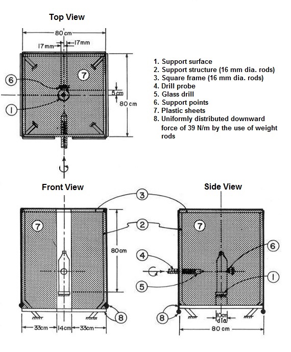
(a) as illustrated in the figure of the test apparatus, provide
(i) a flat and horizontal support surface that is 10 cm in diameter,
(ii) on a supporting structure of four corner posts 16 mm in diameter, four straight rods 16 mm in diameter, forming a square frame with outside dimensions of 80 cm for each side centred on the vertical centreline through the support surface and parallel to, and with the upper edges of the rods 80 cm above, the support surface,
(iii) a drill probe of adjustable height, with a horizontal axial centreline in a vertical plane that passes equidistant between two opposite sides of the square frame,
(iv) a sharp “MM Glazemaster Glass Drill, 4.5 mm, Type A”, affixed to and axially centred on the drill probe,
(v) a drill probe drive mechanism capable of rotating the probe 0.2 revolutions per second while advancing the drill 0.254 mm per second towards the vertical centreline through the support surface, and
(vi) two support points for the container of adjustable height, located and oriented as shown in the figure;
(b) cover the top and the four vertical sides of the supporting structure using clear polyethylene plastic sheets of a thickness of 0.035 ± 0.005 mm, and using supplementary means of attachment as required, so that
(i) a single sheet of plastic, 80 cm wide, is suspended across the side facing the drill probe,
(ii) two sheets of plastic, each 33 cm wide, are suspended on the side where the drill probe is located with a gap of 14 cm between the two sheets, symmetrical with the drill probe centreline,
(iii) a single sheet of plastic, 80 cm wide, is suspended across the top and the other two sides,
(iv) the lower edges of the plastic sheets extend below the plane of the support surface, and
(v) the lower edges of the plastic sheets are subjected to a uniformly distributed downward force of 39 N/m of width by the use of weight rods;
(c) remove from the container any packaging and label that does not remain on it after its sale and during its use;
(d) ensure that the unopened container is equilibrated to a test temperature by storing it in a water bath at 22°C for four hours and is equilibrated as to pressure at that temperature by ultrasonic agitation immediately before the test;
(e) ensure that the plastic sheets are free of any perforation;
(f) adjust the drill probe and the support points to the mid-height of the container;
(g) place the container upright and unopened on the support surface and against the support points;
(h) adjust the probe drive mechanism to a linear velocity of 0.254 mm per second and a rotational velocity of 0.2 revolutions per second, and advance the drill probe until it pierces the container; and
(i) if the container shatters, note whether any piece or part of the container has perforated the plastic sheets above the horizontal plane of the support surface.
Figure — Test Apparatus
SCHEDULE 2(Section 3)Drop Test — Distance of Projection
1 The following method is to be used to test the distance of projection of a carbonated beverage glass container that has shattered:
(a) as illustrated in the figure of the test apparatus, provide
(i) a block of concrete, 50 cm long, 40 cm wide and 20 cm high, having a smooth, flat and horizontal impact surface, positioned on a flat and horizontal concrete base,
(ii) a rigid cylinder, with an inside diameter of 2 m and a height of 20 cm, placed vertically on the concrete base so that it is concentric with the concrete block, and the upper edge of the cylinder is in the plane of the impact surface, and
(iii) a drop mechanism, consisting of two horizontal support bars of 6 mm diameter with their centrelines 4 cm apart positioned symmetrically over the longitudinal centreline of the impact surface and with their upper edges 75 cm above the impact surface, capable of permitting a free fall of the container from its horizontal support position by a snap action withdrawal of the two support bars in symmetrical paths downward and away from the container while maintaining the bar centrelines horizontal;
(b) remove from the container any packaging and label that does not remain on it after its sale and during its use;
(c) ensure that the unopened container is equilibrated to a test temperature by storing it in a water bath at 25°C for four hours and is equilibrated as to pressure at that temperature by ultrasonic agitation immediately before the test;
(d) clear and clean the area inside and outside the cylinder;
(e) place the container horizontal and unopened, centred between and on the support bars, with the vertical plane through the mid-height of the container passing through the transverse centreline of the impact surface;
(f) activate the drop mechanism allowing the container to fall freely on the impact surface;
(g) if the container shatters,
(i) collect, clean, dry and weigh all pieces and parts of the container, including the top and label, that have travelled beyond the outside diameter of the cylinder, and
(ii) collect, clean, dry and weigh all pieces and parts of the container, including the top and label, that have remained within the inside diameter of the cylinder; and
(h) calculate the dry weight of the container by adding the weights obtained in subparagraphs (g)(i) and (ii).
Figure — Test Apparatus

Page Details
- Date modified: