
Radiation Emitting Devices Regulations (C.R.C., c. 1370)
Full Document:
- HTMLFull Document: Radiation Emitting Devices Regulations (Accessibility Buttons available) |
- XMLFull Document: Radiation Emitting Devices Regulations [401 KB] |
- PDFFull Document: Radiation Emitting Devices Regulations [982 KB]
Regulations are current to 2026-05-26 and last amended on 2025-10-09. Previous Versions
SCHEDULE II(Section 3)
PART ITelevision Receivers
Interpretation
1 In this Part,
- maximum test voltage
maximum test voltage means
(a) 127 volts, if the television receiver is designed to operate from a 110-120 volt power source, or
(b) 110 per cent of the maximum voltage from which the television receiver is designed to operate, if the television receiver is designed to operate otherwise than from a 110-120 volt power source; (tension maximale d’essai)
- service control
service control means a control that is installed on a television receiver by the manufacturer thereof for the purpose of adjustment and that, under normal usage, is not accessible to the user of the receiver; (commande interne)
- user control
user control means a control that is provided on or external to a television receiver by the manufacturer thereof for the purpose of adjustment and that for a fully assembled television receiver under normal usage, is accessible to the user. (commande externe)
Standards of Design and Construction
2 (1) Every television receiver shall be designed and constructed in such a way that
(a) under normal conditions of use, and
(b) on failure or malfunction of any one component or subsequent failure or malfunction of other components caused by that failure or malfunction,
it functions in accordance with the standards of functioning described in section 3 for as long as the receiver has its original components or has replacement components recommended by the manufacturer.
(2) Without limiting the generality of subsection (1), the components of a receiver that emit X-rays shall have sufficient shielding to enable the receiver to comply with the standards of functioning set out in section 3.
(3) Where the shielding required by subsection (2) necessitates the use of individual shields, such shields shall either
(a) be non-removable, or interlocked; or
(b) bear a radiation warning sign that is permanently affixed and clearly visible under the conditions of servicing, and cautions against operation of the receiver when the shield is removed.
(4) Subject to subsection (6), every television receiver shall bear on the rear external surface of its cabinet or case, a permanent label that sets out, with respect to the receiver
(a) the name and address of the manufacturer;
(b) the model number;
(c) the city and country of manufacture or a code by which that city and country are identified and the key to which is supplied by the manufacturer to the Minister before the sale of the receiver;
(d) the month and year of manufacture, without abbreviation, with the year shown as a four-digit number;
(e) the brand name of the receiver;
(f) the chassis family designation; and
(g) the serial number.
(5) The permanent label required by subsection (4) shall be clearly visible at any time.
(6) Where a television receiver is manufactured for sale under the trade name of a person who is not the manufacturer of the receiver, the trade name and the address of that person may, for the purposes of paragraph (4)(a), be substituted for the name and address of the manufacturer if the name and address of the manufacturer are permanently affixed to the inside of the cabinet or case of the receiver and are clearly visible under conditions of servicing.
(7) and (8) [Revoked, SOR/94-40, s. 1]
Standards of Functioning
3 Every television receiver shall function in such a way that
(a) when the receiver
(i) is fully assembled,
(ii) is used with any supply voltage up to the maximum test voltage,
(iii) is used with any settings of the user controls and service controls, and
(iv) displays a synchronous raster covering at least 60 per cent of the viewable screen area,
the emission of ionizing radiation therefrom is such that the exposure rate of X-rays, when averaged over a period of five minutes, to an object having a 10 square centimetre cross section and centred at five centimetres from any accessible external surface of the television receiver does not exceed 0.5 milliroentgen per hour; and
(b) when the receiver, without its cabinet or case, or any part of the chassis, cabinet or case,
(i) is used with any supply voltage up to the maximum test voltage,
(ii) is used with any settings of the user controls and service controls, and
(iii) displays a synchronous raster covering at least 60 per cent of the viewable screen area,
the emission of ionizing radiation therefrom is such that the exposure rate of X-rays, when averaged over a period of five minutes, to an object having a 10 square centimetre cross section and centred at 10 centimetres from the surface of any component of the receiver does not exceed 2.5 milliroentgen per hour.
PART IIDental X-Ray Equipment
Interpretation
Marginal note:Definitions
1 The following definitions apply in this Part.
- aluminum
aluminum means aluminum that has a degree of purity of 99.9% or higher and a density of 2.70 g/cm3. (aluminium)
- aluminum equivalent
aluminum equivalent means the attenuation equivalent of an object, expressed in thickness of aluminum. (équivalent en aluminium)
- coefficient of variation
coefficient of variation means the ratio of the estimated standard deviation to the mean value of a series of measurements, determined by the formula
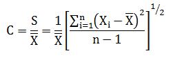
where
- C
- is the coefficient of variation;
- S
- is the estimated standard deviation;
- is the mean value of the measurements;
- Xi
- is the value of the ith measurement; and
- n
- is the number of measurements. (coefficient de variation)
- dental volumetric reconstruction
dental volumetric reconstruction means reconstruction of the three-dimensional attenuation distribution of all or part of the irradiated volume from a series of two-dimensional projections that are produced by an X-ray beam on an X-ray image receptor moving around the head of a patient. (reconstruction dentaire volumétrique)
- deviation
deviation, in respect of any parameter of dental X-ray equipment, means the percentage error between the measured value and the value indicated either on the equipment or in the accompanying information. (variation)
- digital X-ray image receptor
digital X-ray image receptor means an X-ray image receptor that has a conversion method which is electrically powered. The conversion method may include single-step direct conversion or multi-step indirect conversion. (récepteur numérique d’image radiologique)
- effective image reception area
effective image reception area means the part of the image reception area that is configured to receive an X-ray pattern that can be processed for display or storage. (surface réceptrice de l’image efficace)
- extra-oral
extra-oral, in relation to dental radiography, means that the X-ray image receptor is located outside the oral cavity. (extra-oral)
- hand-held
hand-held, in respect of transportable dental X-ray equipment, means that the equipment, once it is placed into service, is held in or supported by the hand. (portatif)
- intra-oral
intra-oral, in relation to dental radiography, means that all or part of the X-ray image receptor is located inside the oral cavity. (intra-oral)
- irradiation time
irradiation time means the duration of an irradiation, measured as the interval between the instant when the air kerma rate rises for the first time to a value of 50% of the peak value and the instant when it drops for the last time below 50% of the peak value. (temps d’irradiation)
- lead equivalent
lead equivalent means the attenuation equivalent of an object, expressed in thickness of lead. (équivalent en plomb)
- loading factor
loading factor means a factor the value of which influences the X-ray tube load. It includes the following:
(a) in the case of an X-ray beam that is produced by the discharge of the capacitor through an X-ray tube, the X-ray tube voltage and the amount of capacitor charge;
(b) in the case of a field emission device in which the emission of electrons from the cathode is due solely to the action of an electric field, the X-ray tube voltage and the number of pulses; and
(c) in any other case, the X-ray tube voltage and either
(i) the X-ray tube current and irradiation time, or
(ii) the current time product. (paramètre de charge)
- mode of operation
mode of operation means the technical state that is defined by a configuration of several predetermined loading factors and other settings for radiography or radioscopy, selectable simultaneously by the operation of a single control. (mode de fonctionnement)
- rectification type
rectification type means the process by which the X-ray generator of dental X-ray equipment converts high voltage to X-ray tube voltage. (type de redressement)
- transportable
transportable, in relation to dental X-ray equipment, means that the equipment is constructed so that, once it is placed into service, it is capable of being moved from one place to another. (transportable)
- X-ray field
X-ray field means the area on a surface that is intersected by a radiation beam whose boundary is determined by the points where the air kerma drops to 25% of the air kerma at the centre of the area. (champ de rayonnement X)
- X-ray image receptor
X-ray image receptor means a device that converts incident X-rays into a visible image or into a form that can be made into a visible image. (récepteur d’image radiologique)
Information and Labelling
Information
Marginal note:General requirements
2 The manufacturer, distributor and importer must ensure that all of the following information accompanies each piece of dental X-ray equipment:
(a) the manufacturer’s name and civic address, and its postal address if different;
(b) the model designation of the equipment;
(c) the installation instructions;
(d) any radiological safety procedures and additional precautions that are necessary because of any unique features of the equipment;
(e) instructions for use that include
(i) a description of the influence of the main settings or selections that are available to the operator on the radiation dose to the patient,
(ii) if protection of the operator is affected by distance from the equipment, information on the impact of distance on the radiation dose, and
(iii) all information necessary to minimize the operator’s exposure to radiation;
(f) maintenance instructions;
(g) procedures for quality control testing to be performed on the equipment, including how often the tests are to be performed and the acceptance criteria;
(h) for each X-ray tube assembly,
(i) the nominal focal spot sizes,
(ii) the cooling curves for the anode and for the X-ray tube housing,
(iii) the X-ray tube rating charts, and
(iv) the focal spot position;
(i) the duty cycles, its rectification type and its generator rating;
(j) the nominal line voltage, the maximum line current and the line voltage regulation that are necessary to operate the equipment at the maximum line current;
(k) the loading factors that constitute the maximum line current condition for the X-ray generator;
(l) the recommended loading factors for each patient size;
(m) when combinations of loading factors are indicated on the control panel by either a single reference to the combination or the value of only one of the loading factors that makes up the combination, the values of all the loading factors for each combination;
(n) if the equipment can operate in automatic exposure control mode,
(i) the accuracy limits of the automatic exposure control,
(ii) the nominal shortest irradiation time in that mode, and
(iii) the reproducibility of the air kerma relative to the range of loading factors, as the loading factors are adjusted by the automatic exposure control;
(o) if the equipment can operate in a mode other than automatic exposure control mode, the operating range and the maximum deviation for any setting within the operating range for each loading factor;
(p) if the equipment is battery-powered, the minimum state of charge that is necessary for it to operate;
(q) if removable protective devices are specified for use with the equipment by the manufacturer, information about their effectiveness, application and use;
(r) if dosimetric indications are displayed on the equipment, information and instructions on how to check and maintain their accuracy; and
(s) for transportable equipment, recommendations for secure storage of the equipment against theft and unauthorized use.
Marginal note:Additional requirements — intra-oral equipment
3 In addition to the requirements set out in section 2, the manufacturer, distributor and importer must ensure that all of the following additional information accompanies each piece of intra-oral dental X-ray equipment:
(a) the shape and dimensions of the exit field;
(b) in the case of equipment that has a digital X-ray image receptor,
(i) a description of the minimum performance criteria for the device that is used to display the images for diagnostic purposes,
(ii) the nominal X-ray image receptor air kerma range that is needed for the intended use, and
(iii) recommendations for typical loading factors at specified distances between the focal spot and the skin to achieve the air kerma referred to in subparagraph (ii);
(c) the method by which the distance between the focal spot and the skin can be determined using the indicator specified in paragraph 7(f);
(d) if the air kerma is indicated on the equipment, the maximum deviation;
(e) if the air kerma is not indicated on the equipment,
(i) the air kerma at a given distance from the focal spot for every selectable combination of loading factors, and
(ii) the maximum deviation of the air kerma;
(f) a method to calculate the dose area product using the air kerma and the exit field size; and
(g) in the case of hand-held equipment,
(i) values for the leakage radiation at the operator’s position and the method to assess the leakage radiation,
(ii) guidance on how to avoid image degradation caused by motion of the X-ray source assembly during loading and the methods to assess the degradation, and
(iii) the designation of a significant zone of occupancy, as follows:
(A) dimensions of at least 60 cm x 60 cm with a height of at least 200 cm,
(B) a drawing that indicates the boundaries of the zone in relation to clearly recognizable features of the equipment,
(C) at least one profile of stray radiation in the zone with respect to the height above the floor — under representative operating conditions indicated — and that includes the point that receives the highest dose, and
(D) a description of the testing methodology used to determine the profiles of stray radiation, including instructions for achieving the loading factors used in the testing if they are controlled only by an automatic control system.
Marginal note:Additional requirements — extra-oral equipment
4 In addition to the requirements set out in section 2, the manufacturer, distributor and importer must ensure that all of the following additional information accompanies each piece of extra-oral dental X-ray equipment:
(a) a description of the geometric relationship between the focal spot, X-ray beam dimensions, patient position and image reception area;
(b) if the air kerma is indicated on the equipment, the maximum deviation;
(c) if the air kerma is not indicated on the equipment,
(i) the air kerma at the entrance of the X-ray image receptor for every selectable combination of loading factors, and
(ii) the maximum deviation of the air kerma;
(d) the maximum deviation of the dose area product;
(e) instructions on how to identify the location and dimensions of the effective image reception area;
(f) for equipment in which any of the loading factors set out in items 1 to 3 and 5, column 1, of the table to subsection 30(1) vary during an irradiation, instructions on how to measure the deviation and on how to compare it with the maximum deviation set out in column 2 of that table; and
(g) if a precalculated or measured current time product is indicated on the equipment, the lowest current time product or the combinations of loading factors that result in the lowest current time product.
Labelling
Marginal note:Presentation
5 The manufacturer, distributor and importer must ensure that all information that is required by this Part to be displayed on dental X-ray equipment is set out in a permanent, clear and legible manner on the specified surface of the equipment when it is fully assembled for use.
Marginal note:Function of controls
6 The manufacturer must ensure that all controls, warning lights and other indicators on the control panel are clearly labelled as to their function.
Marginal note:Displayed information
7 The manufacturer must ensure that all of the following information is displayed on dental X-ray equipment:
(a) on the external surface of the control panel,
(i) a statement that unauthorized use of the equipment is prohibited,
(ii) a warning that hazardous X-rays are emitted when the equipment is in use, and
(iii) one of the X-ray warning symbols set out in section 8;
(b) on an external surface of the equipment,
(i) the name of its manufacturer,
(ii) its model designation,
(iii) its serial number,
(iv) the date of its manufacture, and
(v) the country where it was manufactured;
(c) on or near the external surface of the control panel — when combinations of loading factors are indicated on the control panel by either a single reference to the combination or the value of only one of the loading factors that makes up the combination — the values of all the loading factors for each combination;
(d) on the external surface of the X-ray source assembly, with respect to the X-ray tube,
(i) the name of its manufacturer,
(ii) the model designation,
(iii) its serial number, and
(iv) the country of its manufacture;
(e) on the external surface of the X-ray source assembly, the permanent filtration of the X-ray source assembly, expressed at a specified X-ray tube voltage either in millimetres of aluminum equivalent or as the thickness of any other material, together with its chemical symbol;
(f) on the external surface of the X-ray source assembly, a mark that indicates the location along the X-ray beam axis of the focal spot on the anode target;
(g) on the surface of any detachable beam-limiting device,
(i) the name of its manufacturer,
(ii) its model designation,
(iii) its serial number,
(iv) its quality equivalent filtration, if it is more than 0.2 mm aluminum equivalent, expressed at a specified X-ray tube voltage either in millimetres of aluminum equivalent or as the thickness of another material together with its chemical symbol, and
(v) in the case of intra-oral equipment, its exit field size;
(h) on the external surface of every fixed layer of material in the path of the X-ray beam incident on the patient — excluding any added filters and non-removable materials in the X-ray tube assembly — the quality equivalent filtration, if it is more than 0.2 mm aluminum equivalent, expressed at a specified X-ray tube voltage either in millimetres of aluminum equivalent or as the thickness of another material together with its chemical symbols; and
(i) on the external surface of the X-ray tube housing of hand-held intra-oral equipment, the words
“WARNING: Hand-held operation increases operator radiation exposure due to proximity. See manufacturer safety information.”
« ATTENTION : L’utilisation de l’appareil en mode portatif augmente l’exposition de l’opérateur au rayonnement en raison de la proximité. Consultez les renseignements de sécurité du fabricant. »
Marginal note:Warning symbol
8 The X-ray warning symbol must have the following characteristics:
(a) it must be displayed in two contrasting colours;
(b) it must be visible and identifiable from a distance of 1 m;
(c) it must be at least 2 cm high and at least 2 cm wide;
(d) it must bear the words “CAUTION: X-RAYS — ATTENTION : RAYONS X”; and
(e) it must conform to one of the following:
(i) the X-ray warning symbol:

(ii) the symbol ISO 361 in the report of the International Electrotechnical Commission entitled Graphical symbols for electrical equipment in medical practice, Publication IEC TR 60878: 2015, Third Edition, illustrated as follows:

(iii) the symbol ISO 7010-W003 in the report of the International Electrotechnical Commission entitled Graphical symbols for electrical equipment in medical practice, Publication IEC TR 60878: 2015, Third Edition, illustrated as follows:
Construction and Functioning Standards
Marginal note:Control panel
9 The control panel of dental X-ray equipment must have all of the following features:
(a) a visual indicator that warns the operator when one further actuation of a control will initiate the emission of X-rays;
(b) a visual indicator that warns the operator when X-rays are being emitted and that is clearly visible during the emission;
(c) if the equipment can emit X-rays while not in automatic exposure control mode, controls and visual indicators that enable the operator to select the loading factors or mode of operation before initiation of the irradiation;
(d) if more than one X-ray source assembly is controlled by the same control panel, a visual indicator that shows, before initiation of the irradiation, which of the X-ray source assemblies is connected and ready to emit X-rays;
(e) if the equipment allows for the selection of added filters by remote control or an automatic system, a visual indicator that shows which filter has been selected;
(f) if the equipment is battery-powered, a visual indicator that shows whether the battery is adequately charged for the proper operation of the equipment;
(g) for extra-oral equipment, an indicator that displays the dose area product; and
(h) for extra-oral equipment, an indicator that displays the air kerma at the entrance of the X-ray image receptor, unless the air kerma is already provided in the accompanying information required by section 4.
Marginal note:Irradiation switch — functions
10 (1) Every irradiation switch of dental X-ray equipment must enable all of the following functions:
(a) to initiate and to end an irradiation;
(b) to permit the emission of X-rays only when the operator exerts continuous pressure on the switch;
(c) to operate in a way that it is not possible to initiate an irradiation without first releasing the switch by which the previous irradiation was initiated; and
(d) except in the case of hand-held intra-oral equipment, to permit the operator to stand at least 2 m from the X-ray source assembly when the X-ray tube is energized.
Marginal note:Hand-held intra-oral equipment
(2) Hand-held intra-oral equipment must also be equipped with a second irradiation switch, whether attached or remote, that gives the operator the option to stand at least 2 m from the X-ray source assembly when the equipment is supported on a stand.
Marginal note:Protected area
11 Dental X-ray equipment, except transportable equipment, must have a means to permit initiation of an irradiation by the operator from an area that is protected from radiation by structural shielding or distance.
Marginal note:Audible signal
12 Dental X-ray equipment must emit a signal, clearly audible to the operator, that indicates the end of an irradiation.
Marginal note:Line voltage fluctuations
13 Dental X-ray equipment must have a means appropriate to its rectification type to compensate for variations in X-ray tube voltage that are caused by line voltage fluctuations.
Marginal note:X-ray tube
14 The X-ray tube of dental X-ray equipment must be securely affixed to and aligned within the X-ray tube housing.
Marginal note:X-ray source assembly
15 The X-ray source assembly of dental X-ray equipment must maintain its required position or trajectory without drift or vibration during operation.
Marginal note:Multiple X-ray source assemblies
16 If more than one X-ray source assembly of dental X-ray equipment is controlled by the same control panel, the equipment must have a visual indicator on or near each X-ray tube housing that shows which of the X-ray source assemblies has been selected.
Marginal note:Filtration
17 (1) Dental X-ray equipment must have radiation-absorbing filters that meet the following requirements:
(a) the filters must be securely affixed to the exit port of the X-ray tube housing or to the beam-limiting device, or to both; and
(b) the filters must provide the following degree of attenuation of the X-ray beam:
(i) for each X-ray tube voltage peak value set out in column 1 of the table to this subsection, a first half-value layer of aluminum that is not less than the value set out in column 2, and
(ii) in any other case, a first half-value layer of aluminum that is not less than the value obtained by linear interpolation or extrapolation from that table.
TABLE
Column 1 Column 2 Item X-ray Tube Voltage — Peak Value (kV) First Half-value Layer of Aluminum (mm) 1 60 2.2 2 70 2.5 3 80 2.9 4 90 3.2 5 100 3.6 6 110 3.9 7 120 4.3 8 130 4.7 9 140 5.0 10 150 5.4
Marginal note:Total filtration — intra-oral equipment
(2) Despite paragraph (1)(b), if intra-oral dental X-ray equipment operates at a maximum nominal X-ray tube voltage of 70 kV or less, it may have a total filtration of at least 1.5 mm aluminum equivalent.
Marginal note:Automatic exposure control
18 Dental X-ray equipment that has an automatic exposure control must have the following features:
(a) a means to automatically end the irradiation when,
(i) in the case of extra-oral equipment, either
(A) the product of the X-ray tube voltage, X-ray tube current and irradiation time exceeds 64 kJ per irradiation, or
(B) the current time product exceeds 640 mAs per irradiation, and
(ii) in the case of intra-oral equipment, either
(A) the product of the X-ray tube voltage, X-ray tube current and irradiation time exceeds 3.2 kJ per irradiation, or
(B) the current time product exceeds 32 mAs per irradiation;
(b) a visual indicator or audible signal to warn the operator that the irradiation has ended because one of the limits set out in paragraph (a) has been reached; and
(c) a reset control that must be activated manually once one of the limits set out in paragraph (a) has been reached and before another irradiation under automatic exposure control can be initiated.
Marginal note:Minimum distance — focal spot to skin
19 The minimum distance between the focal spot and the skin must be
(a) 15 cm, in the case of extra-oral equipment; and
(b) 20 cm, in the case of intra-oral equipment.
Marginal note:Maximum deviation — focal spot to image receptor
20 If the distance between the focal spot and the X-ray image receptor of extra-oral dental X-ray equipment is adjustable, the equipment must have a visual indicator that shows the distance that is selected and that has a maximum deviation of 5%.
Marginal note:Beam-limiting device — extra-oral equipment
21 (1) Extra-oral dental X-ray equipment must have a beam-limiting device that meets the following requirements:
(a) when used for dental volumetric reconstruction with a circular image reception area, the device must operate so that
(i) the X-ray field does not exceed the boundary of the effective image reception area by more than 2 cm, measured along any diameter, and
(ii) at least 90% of the area of the X-ray field overlaps the effective image reception area;
(b) when used for dental volumetric reconstruction with a rectangular image reception area, the device must operate so that
(i) along each of the two axes of the image reception area, the edges of the X-ray field do not exceed the corresponding edges of the effective image reception area by more than 2 cm or 3% of the indicated distance between the focal spot and the image receptor, whichever is larger, when the image reception plane is perpendicular to the X-ray beam axis, and
(ii) the sum of the discrepancies on both axes does not exceed 3 cm or 4% of the indicated distance between the focal spot and the X-ray image receptor, whichever is larger;
(c) when used for projection radiography, the device must operate so that the X-ray field does not exceed the boundary of the effective image reception area; and
(d) when used for narrow beam scanning radiography, the device must operate so that
(i) along the axis of the image reception area that is parallel to the direction of the scanning, the X-ray field does not exceed the boundary of the effective image reception area by more than 1 mm on each side, and
(ii) along the axis of the image reception area that is perpendicular to the direction of the scanning, the X-ray field does not exceed boundary of the effective image reception area.
Marginal note:Beam-limiting device — intra-oral equipment
(2) Intra-oral dental X-ray equipment must have a beam-limiting device that meets the following requirements:
(a) the device limits the X-ray field to a circle of not more than 6 cm diameter, measured at the point at which the beam exits the equipment;
(b) if the device has an optional means to limit the exit field to a rectangular shape, it must operate so that the rectangle fits inside that circle;
(c) if the device has a rectangular exit field, it must operate so that the exit field can rotate with respect to the X-ray beam axis; and
(d) in the case of equipment that has an integrated direct digital X-ray image receptor, the device has a means to limit the X-ray field to a rectangular shape that does not exceed the boundary of the effective image reception area by more than 1 cm in the diagonal.
Marginal note:Incremental settings
22 When irradiation times are 0.08 s or greater, the range of settings for the X-ray tube current, irradiation time or current time product of dental X-ray equipment must be in increments that are not greater than the decimal multiples and submultiples of 1.00, 1.25, 1.60, 2.00, 2.50, 3.20, 4.00, 5.00, 6.30 and 8.00.
Marginal note:Modes of operation
23 Dental X-ray equipment that has more than one mode of operation must be constructed in accordance with the following requirements:
(a) in the case of extra-oral equipment that does not have an integrated direct digital X-ray image receptor, the step size of the adjustment between adjacent settings of the current time product must not be greater than 1.6 mAs; and
(b) in the case of intra-oral equipment,
(i) the step size of the adjustment between adjacent settings of the current time product must not be greater than 1.6 mAs, and
(ii) the ratio of the maximum to minimum current time product settings must be at least 4:1.
Marginal note:Current time product
24 For each selectable X-ray tube voltage of intra-oral dental X-ray equipment, the ratio of the maximum to minimum current time product settings must be at least 16:1.
Marginal note:Primary shielding
25 Extra-oral dental X-ray equipment must have primary protective shielding that completely overlaps the X-ray field and that provides the following minimum attenuation:
(a) 0.5 mm lead equivalent, in the case of a nominal X-ray tube voltage of 90 kV or less; and
(b) 2 mm lead equivalent, in the case of a nominal X-ray tube voltage of more than 90 kV.
Marginal note:Attenuation equivalent
26 All parts of extra-oral dental X-ray equipment that are located in the path of the X-ray beam between the patient and the X-ray image receptor must, when taken together, have an attenuation of not more than 1.2 mm aluminum equivalent, as determined at the highest X-ray tube voltage of the equipment.
Marginal note:Hand-held intra-oral equipment
27 Hand-held intra-oral dental X-ray equipment must have all of the following features:
(a) a permanently affixed backscatter shield that has an attenuation of at least 0.25 mm lead equivalent, as determined at a nominal X-ray tube voltage of 70 kV;
(b) a means to prevent unauthorized operation; and
(c) a means to allow the equipment to be supported in a way that it maintains its position so that it is not necessary for the operator to hold the equipment during operation.
Marginal note:X-ray tube voltage
28 The minimum nominal X-ray tube voltage of dental X-ray equipment must be at least 60 kV.
Marginal note:Functioning requirements
29 Dental X-ray equipment must function in accordance with sections 30 to 35 under the following conditions:
(a) the unloaded line voltage must not vary by more than 1% of its nominal value; and
(b) the line voltage must be regulated so that it does not vary by more than 6% when the line is fully loaded at the maximum rated line current of the equipment.
Marginal note:Loading factors
30 (1) Subject to subsection (2), for any combination of loading factors, the measured value of a loading factor set out in column 1 of the table to this subsection must not deviate from the indicated value by more than the amount set out in column 2.
TABLE
Column 1 Column 2 Item Loading Factor Maximum Deviation 1 X-ray tube voltage 10% 2 X-ray tube current 20% 3 Irradiation time for extra-oral dental X-ray equipment 5% + 50 ms 4 Irradiation time for intra-oral dental X-ray equipment 5% or 20 ms, whichever is greater 5 Current time product for extra-oral dental X-ray equipment 10% + 0.2 mAs Marginal note:Exception — intra-oral equipment
(2) In the case of intra-oral dental X-ray equipment that has a one-peak high-voltage generator, the maximum deviation set out in item 4, column 2, of the table to subsection (1) does not apply when the irradiation time is shorter than 0.1 s.
Marginal note:Coefficient of variation — air kerma
31 (1) For any combination of loading factors of dental X-ray equipment, the coefficient of variation of any five consecutive air kerma measurements — taken at the same point along the X-ray beam axis within a one-hour period — must be 0.05 or less.
Marginal note:Internally powered equipment
(2) Dental X-ray equipment that is internally powered must meet the requirement set out in subsection (1) over the whole range of usable charging levels of the internal supply.
Marginal note:Maximum deviation — air kerma
32 The maximum deviation of the air kerma for dental X-ray equipment must not exceed 50%.
Marginal note:Maximum deviation — dose area product
33 The maximum deviation of the dose area product for extra-oral dental X-ray equipment must not exceed 50%.
Marginal note:Air kerma — linearity
34 (1) Subject to subsection (2), for any selected value of X-ray tube voltage and over the whole range of current time product settings, for any two settings of the current time product that do not differ by more than a factor of 2, the quotients of the average of the air kerma measurements divided by the corresponding indicated current time product must not differ by more than 0.10 times their sum, as determined by the following formula, where X is the quotient of the average of the air kerma measurements divided by the indicated current time product, calculated at each of the two settings of the current time product:
|X1 – X2| ≤ 0.1(X1 + X2)
Marginal note:Exception — intra-oral equipment
(2) In the case of intra-oral dental X-ray equipment that has a one-peak high-voltage generator, the shortest irradiation time in the range of current time product settings is 80 ms.
Marginal note:Leakage radiation — loading state
35 (1) Leakage radiation from the X-ray source assembly of dental X-ray equipment must not exceed the following air kerma rate when the equipment is operated at the nominal X-ray tube conditions of loading that correspond to the maximum specified energy input in one hour:
(a) in the case of extra-oral equipment, 1.0 mGy/h; and
(b) in the case of intra-oral equipment,
(i) 1.5 µGy/h for hand-held intra-oral equipment, and
(ii) 0.25 mGy/h for all other intra-oral equipment.
Marginal note:Detection area
(2) For the purpose of subsection (1), the air kerma rate must be averaged over a detection area of 100 cm2 — of which no linear dimension is greater than 20 cm — that is 1 m from the focal spot.
Marginal note:Leakage radiation — extra-oral equipment in non-loading state
(3) In the case of extra-oral dental X-ray equipment that is not in the loading state, the leakage radiation from the X-ray source assembly must not exceed an air kerma rate of 20 µGy/h.
Marginal note:Detection area
(4) For the purpose of subsection (3), the air kerma rate must be averaged over a detection area of 10 cm2 — of which no linear dimension is greater than 5 cm — that is 5 cm from any accessible surface of the equipment.
PART IIIMicrowave Ovens
Interpretation
1 In this Part and in items 3 of Schedule I,
- cavity
cavity means a structure that encloses and confines a microwave field; (cavité)
- commercial microwave oven
commercial microwave oven means a microwave oven for use
(a) in a restaurant, cafeteria or other commercial establishment,
(b) in an industrial establishment, or
(c) in or with a vending machine; (four à micro-ondes commercial)
- control panel
control panel means the portion of the external surface of a microwave oven on which the user controls are mounted; (panneau de commande)
- conveyor
conveyor means a device that transports material into or within a cavity; (convoyeur)
- door
door, with respect to a cavity, means a movable or removable structure that in the closed position is designed to prevent access to the cavity; (porte)
- effective aperture
effective aperture[Revoked, SOR/84-930, s. 1]
- external surface
external surface, with respect to a microwave oven, means the outside surface of the cabinet or other enclosure of the oven and includes the plane of any exit or entry port for conveyorized ovens; (surface externe)
- interlock
interlock means a component or set of components that prevents the generation of microwave power when access to a cavity is possible; (enclenchement)
- leakage radiation
leakage radiation means any radiation transmitted outside the external surface; (rayonnement de fuite)
- microwave
microwave means an electromagnetic wave with frequency in the range 0.010 GHz to 300 GHz; (micro-onde)
- outer enclosure
outer enclosure means a metal or plastic cover that encloses the mechanical and electronic parts of a microwave oven that, under normal conditions of use, are not accessible to the user of the oven; (enceinte externe)
- response time
response time means the time period in which a radiation meter indicator reaches ninety per cent of its final steady state reading when subjected to a stepped input signal; (temps de réponse)
- service control
service control means a control that is provided by the manufacturer for the purpose of adjustment of the microwave oven and that, under normal conditions of use, is not accessible to the user of the oven; (commande interne)
- stirrer
stirrer means the structure designed to distribute the microwave energy within a cavity; (agitateur)
- user control
user control means a control that is provided by the manufacturer for the purpose of operation of the microwave oven and that, under normal conditions of use, is accessible to the user of the oven; (commande externe)
- water equivalent
water equivalent[Revoked, SOR/79-920, s. 1]
- waveguide
waveguide means a metal tube or duct for transmitting microwave energy. (guide d’ondes)
Standards of Design and Construction
2 (1) Every microwave oven shall be designed and constructed in such a manner that, under the conditions of use specified by the manufacturer, it functions in accordance with section 4 with its original components or replacement components recommended by the manufacturer for at least
(a) 200 000 use cycles or openings and closings of the oven door, in the case of a commercial microwave oven; and
(b) 100 000 use cycles or openings and closings of the oven door, in the case of any other microwave oven.
(2) Every microwave oven shall be designed and constructed to include the following safety features:
(a) for each microwave power source, a device or indicator that provides a visible indication of the status of operation of the oven;
(b) a device to monitor one or more of the interlocks required by paragraph (g) that renders the oven inoperable when a monitored interlock fails or is otherwise rendered inoperable;
(c) where the power can be varied by a user control, an indicator to show the level of microwave power applied to the cavity;
(d) where a total microwave power generating capacity of 25 kilowatts or more is used, a lock on the control panel requiring the insertion of a key before microwave power can be generated;
(e) where access to the cavity is not by a conveyor, a door constructed and positioned so as to ensure that any leakage radiation does not exceed the limits prescribed by section 4;
(f) a covering or baffle arrangement over any viewing screen, vent or access port in the cavity wall, other than any opening through which conveyor borne material enters or leaves the cavity, that prevents the insertion of any object into the cavity while the microwave power source is in operation;
(g) where the oven is equipped with a door as specified in paragraph (e), at least two electrically and mechanically independent interlocks positioned so as to ensure that
(i) the door cannot be opened until the microwave power generating component has been turned off, and
(ii) the microwave power generating component cannot be turned on while the door is open; and
(h) components and shields constructed and positioned so that adjustments to the service controls and user controls to yield maximum possible output do not produce leakage radiation in excess of the limits prescribed by section 4.
(3) Every microwave oven shall have permanently affixed to and clearly visible on its external surface the following information and warning sign:
(a) the name of the manufacturer and the model number, serial number and place of manufacture of the oven;
(b) the type of microwave power generating component and the normal operating voltage, operating frequency and normal maximum output power thereof;
(c) a description of the test load prescribed by paragraph 4(3)(a);
(d) the year and month of manufacture of the oven;
(e) the sign described in section 3; and
(f) where the oven is not a commercial microwave oven, the words “NOT FOR COMMERCIAL USE — NON DESTINÉ À UN USAGE COMMERCIAL”.
(4) Where a microwave oven is equipped with a conveyorized system, a warning sign described in section 3 shall be permanently affixed to its external surface adjacent to each entry and exit port.
(5) Where the generation of X-rays within a microwave in excess of 2.5 milliroentgens per hour averaged over 10 square centimetres is possible while the oven is functioning in accordance with subsection 4(1), an X-radiation warning sign that is clearly visible while the microwave oven is being serviced shall be permanently affixed to the microwave power generating component.
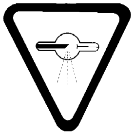
Warning Sign Specifications
3 The warning sign referred to in subsections 2(3) and (4) is a sign that
(a) is shown in two contrasting colours;
(b) is clearly visible and identifiable from a distance of 1 metre;
(c) has no outer dimensions less than 2 centimetres;
(d) bears the words “CAUTION — MICROWAVES” and “ATTENTION — MICRO-ONDES”; and
(e) is designed in accordance with the following diagram:
Standards of Functioning
4 (1) Every microwave oven shall, when fully assembled and operating with its service controls and user controls adjusted to yield the maximum output, function in such a manner that
(a) the leakage radiation, measured with the instrument prescribed by paragraph (3)(b), at all points at least 5 cm from the external surface of the oven, does not exceed
(i) 1.0 mW/cm2 with the test load prescribed by paragraph (3)(a) placed
(A) in the centre of the shelf in the cavity, in the case of an oven that is designed for cooking and that has a total microwave power generating capacity not greater than 1.5 kW, and
(B) as specified by the manufacturer, in the case of an oven other than an oven described in clause (A), and
(ii) 5.0 mW/cm2 without a test load, where the oven is operable in such conditions; and
(b) the intensity of X-ray exposure, at 5 cm from the external surface of the oven, does not exceed 0.5 mR per hour spread over an area of 10 cm2.
(2) Every microwave oven shall, when the outer enclosure is removed and it is operating with its service controls and user controls adjusted to yield the maximum output, function in such a manner that the leakage radiation, measured with the instrument prescribed by paragraph (3)(b) and with the test load prescribed by paragraph (3)(a) in the cavity, at all points at least 5 cm from every mechanical or electronic part of the oven that is accessible to the user of the oven including, but not limited to, the waveguide, cavity, cavity seam, magnetron and magnetron to waveguide connection, does not exceed 5.0 mW/cm2.
(3) For the purposes of subsections (1) and (2),
(a) the test load shall be
(i) in the case of an oven that is designed for cooking and that has a total microwave power generating capacity not greater than 1.5 kW, 275 ± 15 ml of water at an initial temperature of 20 ± 5°C, and
(ii) in the case of an oven other than an oven described in subparagraph (i), the substance and amount thereof specified by the manufacturer as the load to be used for testing the oven; and
(b) the instrument used to measure leakage radiation shall
(i) be capable of measuring a power density of 1.0 mW/cm2 with an accuracy of 2 dB or better, and
(ii) have an indicator with a response time not greater than 3 seconds.
(4) Failure of any single component of a microwave oven shall not cause the interlock system to be inoperative.
(5) The device required by paragraph 2(2)(a) shall have a rated lifetime that is not less than 5,000 hours.
(6) Each interlock required by paragraph 2(2)(g) shall have a rated lifetime that is not less than
(a) 200 000 on-off cycles, in the case of a commercial microwave oven; and
(b) 100 000 on-off cycles, in the case of any other microwave oven.
PART IVBaggage Inspection X-ray Devices
Interpretation
1 In this Part,
- detector
detector means the image receptor or other devices that interacts with the X-rays to produce a signal corresponding to the intensity of the X-rays incident on it; (détecteur)
- model designation
model designation means any combination of letters or figures or both letters and figures by which a device that bears that designation is identified as having characteristics and design features that are uniform; (désignation du modèle)
- primary X-ray beam
primary X-ray beam means that X-radiation emitted directly from the target of the X-ray tube and emerging through the window of the X-ray generator; (faisceau primaire de rayons X)
- X-ray generator
X-ray generator means an assembly of components, including an X-ray tube and its housing and shielding, designed and constructed for the controlled generation of X-rays. (producteur de rayons X)
Standards of Design and Construction
2 (1) A baggage inspection X-ray device shall be designed and constructed in such a way that it functions in accordance with the standards of functioning described in section 3 for as long as the device has its original components or has replacement components recommended by the manufacturer.
(2) Notwithstanding subsection (1), a baggage inspection X-ray device shall have sufficient shielding to enable the device to comply with the standards of functioning described in section 3.
(3) A baggage inspection X-ray device shall be designed and constructed to include the following safety features:
(a) doors or panels over all access openings that are designed for insertion or removal of baggage, unless the device is designed to prevent the insertion of any part of the human body into the primary X-ray beam through those access openings;
(b) interlocking of all doors or panels referred to in paragraph (a), with not less than two independent safety interlocks so that, if any of those doors or panels are opened, X-rays cannot be generated;
(c) interlocking of all doors or panels that allow access to areas where the exposure to X-rays may exceed the level specified in section 3, except those doors or panels referred to in paragraph (a) so that, if any of those doors or panels are opened or removed, X-rays cannot be generated;
(d) separate warning lights or other indicators
(i) that clearly indicate to the operator when the device is powered and when X-rays are being generated,
(ii) designed so that if a pulsed X-ray system is used, the X-rays “ON” lights or indicators remain on for at least 1/2 second, and
(iii) that either
(A) contain built-in duplication so that the requirements of subparagraphs (i) and (ii) are met, if one of the redundant components fails, or
(B) are interlocked so that, if they malfunction, X-rays cannot be generated;
(e) a lock that requires the insertion of a key before X-rays can be produced and that terminates the exposure when the key is removed;
(f) subject to subsection 2(4), a control or controls to initiate the generation of X-rays, requiring separate operator action for each exposure;
(g) the automatic alignment of the X-ray generator with the detector when the device is assembled;
(h) an X-radiation warning sign described in section 4 that
(i) is readily discernible and in clear view of the operator, and
(ii) is permanently affixed to the device at all access openings where baggage is inserted or removed;
(i) a permanent mark or label that is readily discernible and clearly visible on
(i) the external surface of the device, under normal conditions of use, and
(ii) on the external surface of the X-ray generator, under conditions of servicing,
and that will identify the manufacturer, model designation, serial number, and date and place of manufacture of the device.
(4) Paragraph (3)(f) does not apply to a baggage inspection X-ray device that contains a conveyor system if the X-ray exposure, or a sequence of X-ray exposures, is initiated automatically and the device
(a) contains a photocell or other baggage sensing device that initiates X-ray exposures or a sequence of X-ray exposures automatically; and
(b) is designed and constructed to include the following additional safety features:
(i) a control or switch of a type that
(A) requires continuous pressure by the operator to maintain the automatic operation of the device, and
(B) stops the conveyor and terminates the X-ray exposure, or sequence of X-ray exposures, when released, and
(ii) a conveyor of sufficient length to prevent insertion of any part of the human body into any area where the exposure to X-rays exceeds the level specified in section 3.
Standards of Functioning
3 All baggage inspection X-ray devices shall function in such a way that
(a) at the maximum possible baggage handling rate specified by the manufacturer for the device, and
(b) under all operating conditions of X-ray generation,
the average exposure rate of X-rays, averaged over a period that is not less than 5 minutes, to an object having a 10 square centimetre cross section and centered at 5 centimetres, from any accessible external surface of the device or from the imaginary plane surface that is drawn to close openings of the device, where baggage is inserted or removed, does not exceed 0.5 milliroentgen per hour.
Warning Sign
4 The X-radiation warning sign referred to in paragraph 2(3)(h) is a sign that
(a) is shown in two contrasting colours;
(b) is clearly visible and identifiable from a distance of 1 metre;
(c) has no outer dimensions less than 2 centimetres;
(d) bears the words “CAUTION — X-RAYS” and “ATTENTION — RAYONS X”; and
(e) is designed in accordance with the following diagram:
PART VDemonstration-type Gas Discharge Devices
Interpretation
1 In this Part,
- cabinet
cabinet of a device means a structure that encloses and confines the X-ray source of the device and the material to be irradiated in the device; (coffret)
- device
device means a demonstration-type gas discharge device; (dispositif)
- gas discharge tube
gas discharge tube means an electronic tube in which glow discharges or X-rays or both may be produced by the acceleration of electrons or ions; (tube à décharge)
- model designation
model designation means any combination of letters or figures or both letters and figures by which a device that bears that designation is claimed to have characteristics and design features that are uniform. (désignation du modèle)
Standards of Design and Construction
2 Every device that contains a gas discharge tube not specifically designed to generate X-rays shall be designed and constructed to include the following safety features:
(a) a permanent mark or label that
(i) is clearly visible under conditions of normal use,
(ii) identifies the device by setting out the name of the manufacturer, model designation, and date and place of manufacture,
(iii) indicates the intended polarity of each terminal of the device, and
(iv) indicates the power supply or maximum voltage to be used with the device; and
(b) shielding that
(i) is sufficient to enable the device to comply with the standards of functioning set out in section 5, and
(ii) is either non-removable or is so constructed that its removal renders the device inoperable.
3 Subject to section 4, where a device contains a gas discharge tube specifically designed to generate X-rays, that tube shall be enclosed in a cabinet that
(a) has permanently affixed to its external surface
(i) the X-radiation warning sign described in section 6,
(ii) a readily discernible mark or label that
(A) identifies the manufacturer, model designation and date and place of manufacture of the device, and
(B) warns that the tube generates X-rays when energized, and
(iii) where the power source for the device is not an integral part of the device, a mark or label that
(A) is clearly visible under normal conditions of use of the device, and
(B) indicates the intended polarity of the terminals of the device and the power supply or maximum voltage to be used with the device;
(b) is provided with
(i) two warning lights that are in clear view of the operator of the device, one of which indicates when the device is powered and the other of which indicates when X-rays are being generated, and
(ii) shielding that
(A) is sufficient to enable the device to comply with section 5, and
(B) is not removable or is so constructed that its removal renders the device inoperable; and
(c) is constructed so that X-rays cannot be generated by the device when any door or panel in the cabinet that allows access to its interior is opened or removed.
4 (1) Where the power source is not an integral part of the device, the warning light required by subparagraph 3(b)(i) to indicate when the device is powered shall be located on the power source.
(2) The device referred to in section 3 shall be constructed so that, where the warning light required by subparagraph 3(b)(i) to indicate when X-rays are being generated fails or malfunctions,
(a) a duplicate warning light operates when X-rays are being generated; or
(b) X-rays cannot be generated by the device.
Standards of Functioning
5 Every device shall function in such a way that the emission of X-rays therefrom, under all possible conditions of operation and for as long as the device has its original components or has replacement components recommended by the manufacturer, is such that the average exposure rate of X-rays to an object having a 10 square centimetre cross section and centred at 5 centimetres from any accessible external surface of the device does not exceed 0.5 milliroentgen per hour.
Warning Sign
6 The X-radiation warning sign referred to in subparagraph (3)(a)(i) is a sign that
(a) is shown in two contrasting colours;
(b) is clearly visible and identifiable from a distance of 1 metre;
(c) has no outer dimensions less than 2 centimetres;
(d) bears the words “CAUTION — X-RAYS” and “ATTENTION — RAYONS X”; and
(e) is designed in accordance with the following diagram:
PART VIPhotofluorographic X-ray Equipment
Interpretation
1 In this Part,
- attenuation
attenuation means a decrease in radiation intensity caused by absorption and scattering in a medium; (atténuation)
- coefficient of variation
coefficient of variation means the ratio of the standard deviation to the mean value of a series of exposure measurements calculated by using the following equation:

when
- C
- = coefficient of variation
- Xi
- = ith exposure measurement
- = mean value of the exposure measurements
- n
- = number of exposure measurements;
- collimator
collimator means a device or mechanism that limits the shape and size of the useful beam; (collimateur)
- effective focal spot
effective focal spot means the projection of the focal spot on the plane that is perpendicular to the X-ray beam axis and that passes through the centre of the focal spot; (tache focale efficace)
- filter
filter means material placed in the useful beam to attenuate preferentially the lower energy radiations; (filtre)
- focal spot
focal spot means the section at which the anode of an X-ray tube intercepts the electron beam; (tache focale)
- leakage radiation
leakage radiation means all radiation, except the useful beam, coming from within the housing of an energized X-ray generating tube; (rayonnement de fuite)
- useful beam
useful beam means the radiation passing through the aperture, cone or collimator of the housing of an X-ray generating tube. (faisceau utile)
Standards of Design
2 Photofluorographic X-ray equipment shall be designed in such a way that all controls, meters, lights or other indicators are readily discernible and clearly labelled to indicate their function.
3 Photofluorographic X-ray equipment shall be designed to include the following features:
(a) on the control panel, the X-radiation warning sign described in section 6;
(b) a warning sign that
(i) is in clear view of and readily discernible by the operator,
(ii) is permanently affixed to the X-ray control panel,
(iii) indicates the possibility of hazardous radiation emission when the equipment is in operation, and
(iv) prohibits unauthorized use;
(c) electrical meters or other indicators that
(i) are in clear view of the operator,
(ii) are permanently affixed to the X-ray control panel, and
(iii) show
(A) the preset operating kilovoltage of the equipment when used in the phototiming mode,
(B) the preset operating kilovoltage and milliamperage of the equipment when not used in the phototiming mode, and
(C) for battery-operated equipment, the state of charge of the battery;
(d) separate aural or visual indicators on the control panel that
(i) are clearly discernible by the operator, and
(ii) indicate when the X-ray machine is powered and when X-rays are being produced;
(e) where more than one X-ray tube is controlled by one control panel, it shall not be possible to energize more than one X-ray tube at the same time and there shall be
(i) at each X-ray tube housing, a visible indicator that indicates when the tube is connected and ready to be energized,
(ii) at the control panel, a visible indicator that indicates which tube is connected and ready to be energized, and
(iii) at the normal position of the operator, visible indicators that provide the information required by subparagraph (c)(iii);
(f) an exposure switch on the control panel of a kind that requires continuous pressure by the operator to complete the circuit;
(g) a timer so designed that
(i) when the production of X-rays is automatically terminated after a preset time interval,
(A) the preset time interval is clearly indicated,
(B) an exposure cannot be initiated with the timer set to zero or in the OFF position, and
(C) the minimum exposure time is not greater than 1/60 second,
(ii) when the production of X-rays is automatically terminated after the integrated radiation exposure to a photocell or similar component behind the fluorescent screen is measured, there is incorporated in the timer’s electrical circuitry
(A) an aural or visual indicator that indicates clearly to the operator when the phototimer has failed to terminate the exposure, and
(B) a back-up or safety timer, with a maximum setting of 1 second, that will terminate the exposure in the event of phototimer failure, and
(iii) when the production of X-rays is automatically terminated after a preset milliampere-second interval, the minimum milliampere-second interval is no greater than 1 milliampere-second;
(h) a collimator that renders the machine inoperative if a part of the useful beam at the plane of the fluorescent screen extends beyond the useful portion of the fluorescent screen and
(i) where the photofluorographic X-ray equipment is designed for a variable image receptor size and the target to fluorescent screen distance is variable,
(A) the collimator shall be adjustable, and give a rectangular beam,
(B) the alignment of the centre of the useful beam with the centre of the fluorescent screen shall be within two per cent of the target to the fluorescent screen distance,
(C) there shall be an apron (providing attenuation equivalent to 0.25 millimetre lead for a 100 kilovolts (peak) X-ray beam of half value layer 2.7 millimetres of aluminium) on a bracket attached to the bottom of the fluorescent screen mounting that can be swiveled into place to protect the patient’s gonad area from the useful beam,
(D) means shall be provided to ensure that the axis of the X-ray beam can only be perpendicular to the plane of the fluorescent screen, and
(E) a light beam generator shall be incorporated into the collimator assembly
(I) that visually defines the outline of the useful beam, and
(II) that does not permit a misalignment of the visually defined field with the X-ray field along either the length or width of the X-ray field to exceed two per cent of the target to fluorescent screen distance, and
(ii) where the photofluoraphic X-ray equipment is designed for a constant image receptor size and the target to fluorescent screen distance is fixed,
(A) there shall be a shaped lower leaf or an apron on a bracket as described in clause (h)(i)(C) designed to protect the patient’s gonad area from the useful beam,
(B) the alignment of the centre of the useful beam with the centre of the fluorescent screen shall be within two per cent of the target to fluorescent screen distance, and
(C) means shall be provided to ensure that the axis of the X-ray beam can only be perpendicular to the plane of the fluorescent screen;
(i) a filter that
(i) is securely installed in the path of the useful beam, and
(ii) provides attenuation, including inherent filtration, at least equivalent to that afforded by 2.5 millimetres of aluminium at 100 kilovolts (peak);
(j) a readily visible mark on the X-ray tube housing indicating, to within 2 millimetres, the location on the tube housing of the projection, at right angles to the beam axis, of the position of the focal spot on the target;
(k) an effective focal spot size of not greater than 1.5 square millimetres for units designed to operate at not more than 150 kilovolts (peak);
(l) a lock, on the X-ray machine control panel, of a type that requires the insertion of a key before X-rays can be produced and the removal thereof causes termination of the production of X-rays;
(m) an appliance or other means that
(i) ensure that the machine is not able to be operated if the target to fluorescent screen distance is less than 100 centimetres, and
(ii) clearly indicate the target to fluorescent screen distance to within two per cent;
(n) means that allow data to be recorded automatically on to each film;
(o) an interlock on the film holder mechanism that
(i) prevents more than one film exposure being recorded without resetting; and
(ii) prevents the same film frame receiving more than one exposure;
(p) means that prevent the use of films of size smaller than 70 millimetres × 70 millimetres; and
(q) on or near the power-input socket, a statement of power requirements at the maximum line current and, for battery operated units, a statement of charge-use frequency.
Standards of Construction
4 (1) Photofluorographic X-ray equipment shall be constructed in such a way that
(a) the X-ray tube is securely fixed and correctly aligned within the tube housing;
(b) the X-ray tube head maintains its exposure position without drift, tipping or vibration during operation;
(c) the equipment, under normal conditions of use, functions in accordance with the standards described in section 5 for as long as the X-ray machine has its original components or replacement components recommended by the manufacturer;
(d) where there is provision for insertion of a grid, there is a holder containing a label that indicates the grid ratio of the grid used;
(e) mirrors, lenses or other optical components within the camera hood are securely fastened so that optical misalignment cannot occur with normal use;
(f) the camera hood, containing the whole optical system, does not admit light that can fog the film;
(g) any material between the film side of the fluorescent screen and the first optical component does not reduce the light intensity or alter the spectrum of the light emitted from the fluorescent screen;
(h) the front panel at the camera hood, located between the patient and the fluorescent screen, has less than 0.5 millimetre aluminium equivalence measured with an X-ray beam of potential 100 kilovolts (peak) with a half value layer of 2.7 millimetres of aluminium;
(i) the device bears a replaceable label mounted on the camera hood in clear view of the operator, indicating the type and date of insertion of the fluorescent screen; and
(j) when the recommended schedule of maintenance for the device is followed, the device will function in accordance with section 5 for the normal lifetime of the device.
(2) Photofluorographic X-ray equipment shall bear, on the tube housing and on the control panel, a permanent mark or label that
(a) is clearly visible; and
(b) carries, with reference to the X-ray machine and X-ray tube, the name of the manufacturer, the model number, the serial number and the date and place of manufacture.
Standards of Functioning
5 Photofluorographic X-ray equipment when fully assembled for use shall function under normal conditions of use in such a way that
(a) it is not possible to preset the kilovoltage below 70 kilovolts (peak);
(b) the preset kilovoltage of the X-ray tube is maintained or is adjustable to within 3 kilovolts when the line voltage supply varies by plus or minus 10 per cent of its nominal value;
(c) for any combination of kilovoltage, current and time, the coefficient of variation of any 10 consecutive radiation exposures, taken at the same distance within a time period of 1 hour, is no greater than 0.05;
(d) the entrance exposure to a sheet of 99.9 per cent pure copper of dimensions 45 centimetres × 45 centimetres × 1.41 millimetres, placed over the front panel, and phototimed with the exposure taken at 85 kilovolts (peak), does not exceed 50 milliroentgens per exposure to obtain at the centre of the film an optical density above gross fog of not less than 0.5;
(e) at any fixed kilovoltage, the average ratios of milliroentgen exposure to milliampere-seconds obtained at any two consecutive tube current settings do not differ by more than 0.10 times their sum, namely,
1 - 2 ≤ 0.10(1 + 2),
where
- 1 and 2
- are the average milliroentgen per milliampere-second values obtained at each of two consecutive tube current settings;
(f) the leakage radiation from the X-ray tube assembly, when the machine is operated at any kilovoltage and current within the rating of the X-ray tube, is such that the average exposure rate of X-rays to any object having a 100 square centimetre cross-section and centred at 1 metre from the focal spot of the X-ray tube does not exceed 100 milliroentgens in 1 hour; and
(g) emission of ionizing radiation by any component other than the X-ray tube assembly, when the machine is operated at any kilovoltage and current within the rating of the X-ray tube, is such that the average exposure rate of X-rays to any object having a 10 square centimetre cross-section and centred at 5 centimetres from any accessible surface of the device, does not exceed 2.5 milliroentgens per hour.
Warning Sign
6 The X-radiation warning sign referred to in section 3 of this Part is a sign that
(a) is shown in two contrasting colours;
(b) is clearly visible and identifiable from a distance of 1 metre;
(c) has no outer dimensions less than 2 centimetres;
(d) bears the words “CAUTION X-RAYS” and “ATTENTION RAYONS X”; and
(e) is designed in accordance with the following diagram:

PART VIILaser Products
Interpretation
1 The following definitions apply in this Part.
- IEC 60825-1
IEC 60825-1 means the International Electrotechnical Commission standard IEC 60825-1, Edition 3.0, 2014-05, entitled Safety of laser products – Part 1: Equipment classification and requirements. (CEI 60825-1)
- IEC 62471
IEC 62471 means the International Electrotechnical Commission standard IEC 62471, Edition 1.0, 2006-07, entitled Photobiological safety of lamps and lamp systems. (CEI 62471)
- IEC 62471-5
IEC 62471-5 means the International Electrotechnical Commission standard IEC 62471-5, Edition 1.0, 2015-06, entitled Photobiological safety of lamps and lamp systems – Part 5: Image projectors. (CEI 62471-5)
2 For the purposes of this Part
(a) words and expressions used in the standards incorporated by reference have the same meanings as in the Act;
(b) a reference to “plaque” in the French version of IEC 60825-1 is to be read as a reference to étiquette as defined in section 2 of the French version of the Act; and
(c) a reference to “rayonnement” in the French versions of IEC 60825-1, IEC 62471 and IEC 62471-5 is to be read as a reference to radiation as defined in section 2 of the French version of the Act.
Standards of Design, Construction and Functioning
3 (1) Except as otherwise provided in this Part, a laser product must be designed and constructed, and must function, in accordance with the applicable requirements set out in IEC 60825-1, without regard to any other standard incorporated by reference to which it refers.
(2) The following are exempted from subsection (1):
(a) a laser product that is a component or a repair part as set out in clause 1 of IEC 60825-1;
(b) a laser product that is a medical device as defined in section 1 of the Medical Devices Regulations and that belongs to Class II, III or IV in accordance with the classification rules set out in Schedule 1 to those Regulations.
Marginal note:Exception
(3) A laser product referred to in clauses 4 and 5 of IEC 60825-1 with an emission level that does not exceed the accessible emission limit for Class 1 under all conditions of operation, maintenance, service and failure is exempt from clause 6 of IEC 60825-1 and sections 6 to 8 of this Part.
4 (1) Except as otherwise provided in this Part, a laser product that is designed to function as a conventional lamp and that satisfies the criteria referred to in subclause 4.4 of IEC 60825-1 may have its emissions evaluated in accordance with the applicable requirements set out in IEC 62471 or IEC 62471-5.
(2) A laser product referred to in subsection (1) must respect the requirements of that subsection or the requirements of subsection 3(1).
5 The following provisions of IEC 60825-1 do not apply to a laser product:
(a) those relating to the training of personnel referred to in subclause 6.1;
(b) those relating to the protection against non-optical hazards referred to in subclause 6.15.1; and
(c) those relating to the additional requirements for specific laser products referred to in clause 9.
Information and Labelling
General
6 (1) The information referred to in sections 7 and 8 must be provided in both official languages.
Marginal note:Exceptions
(2) The following laser products are exempt from sections 7 and 8:
(a) a laser product that is a component or a repair part, as set out in clause 1 of IEC 60825-1, and
(b) a laser product that is a medical device as defined in section 1 of the Medical Devices Regulations and that belongs to one of Class II, III or IV in accordance with the classification rules set out in Schedule 1 to those Regulations.
Information
7 (1) Except as otherwise provided in this Part, the manufacturer, distributor and importer of a laser product must ensure that the product is accompanied by the information described in subclause 8.1 of IEC 60825-1 or, if applicable, the information described in subclauses 6.6 and 6.7 of IEC 62471-5.
(2) The information described in items 8.1a), c), f) and i) of IEC 60825-1 is required for a laser product with an “accessible emission”, as defined in subclause 3.2 of that standard, during operation, maintenance or service, that is greater than that of a Class 3R laser product, as determined in accordance with item 5.3d) of that standard.
(3) The requirements for additional information under subclause 8.2 of IEC 60825-1 do not apply to a laser product.
Labelling
8 (1) A laser product must bear labels that meet the requirements of clause 7 of IEC 60825-1 or, if applicable, subclause 6.5 of IEC 62471-5.
(2) A laser product designed to function as a conventional lamp must be labelled in accordance with the requirements of subclause 4.4 of IEC 60825-1 and, if applicable, subclauses 6.5 and 6.7 of IEC 62471-5.
(3) In addition to the information referred to in subclause 4.4 and clause 7 of IEC 60825-1, the labels of a laser product, including one designed to function as a conventional lamp, must contain
(a) the manufacturer’s name and the civic address of its principal place of business;
(b) the model number of the product;
(c) the date of manufacture of the product; and
(d) if the product is imported for sale or lease, the distributor’s name and the civic address of its principal place of business in Canada.
(4) Despite section 6, the information referred to in paragraphs (3)(a) to (d) must be shown in at least one official language.
PART VIII[Repealed, SOR/2024-196, s. 4]
PART IXLow Energy Electron Microscopes
Interpretation
1 In this Part,
- service control
service control means a control that
(a) is installed by the manufacturer on a low energy electron microscope or on any accessory thereof for the purpose of adjustment, and
(b) under normal conditions of use, is not accessible to the user; (commande interne)
- user control
user control means a control that
(a) is provided by the manufacturer on a low energy electron microscope or on any accessory thereof for the purpose of adjustment, and
(b) in the case of a fully assembled low energy electron microscope under normal conditions of use, is accessible to the user. (commande externe)
Standards of Design and Construction
2 Every low energy electron microscope shall be designed in such a way that
(a) all marks, labels and signs are permanently affixed and clearly visible;
(b) all user controls, meters, lights or other indicators are readily discernible and clearly labelled as to function; and
(c) it bears on the external surface
(i) a mark or label that sets out with respect to the device
(A) the name and address of the manufacturer,
(B) the model designation,
(C) the serial number, and
(D) the date of manufacture, and
(ii) the X-radiation warning sign described in section 6.
3 Every low energy electron microscope shall be designed and constructed in such a way that it functions in accordance with the standards of functioning described in section 5 for as long as the device has its original components or has replacement components recommended by the manufacturer.
4 Every low energy electron microscope shall be designed and constructed to include the following safety features:
(a) shielding, if necessary, that
(i) is sufficient to enable the device to comply with the standards of functioning set out in section 5, and
(ii) is either non-removable or is so constructed or connected that its removal renders the device inoperable;
(b) any door or panel that allows access to areas where the exposure to X-rays may exceed the level specified in section 5 is connected in such a way that, if that door or panel is opened or removed, the device cannot function;
(c) accessory ports, if any, are provided with shielded covers that are interlocked in such a way that, if a cover is removed, the device cannot function unless the accessory for which the port is intended is in place;
(d) any accessory provided with or intended for use with the device is shielded in accordance with paragraph (a).
Standards of Functioning
5 Every low energy electron microscope shall function in such a way that
(a) at all settings of the user controls and service controls, and
(b) under all possible modes of operation,
the exposure rate of X-rays to an object having a 10 square centimetre cross section and centred at 5 centimetres from any accessible external surface of
(c) the device, and
(d) any accessory provided for use with the device,
does not exceed 0.5 milliroentgen per hour.
Warning Sign Specification
6 The X-radiation warning sign referred to in paragraph 2(c) is a sign that
(a) is shown in two contrasting colours;
(b) is clearly visible and identifiable from a distance of 1 metre;
(c) has no outer dimensions less than 2 centimetres;
(d) bears the words “CAUTION, X-RAYS” and “ATTENTION, RAYONS X”; and
(e) is designed in accordance with the following diagram:
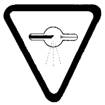
PART XHigh Intensity Mercury Vapour Discharge Lamps
Interpretation
1 In this Part,
- cumulative operating time
cumulative operating time means the sum of the periods of time during which electric current passes through the high-pressure arc discharge tube of a lamp; (durée cumulée de fonctionnement)
- lamp
lamp means any high intensity mercury vapour discharge lamp; (lampe)
- lamp container
lamp container means a carton, wrapper or other package in which a lamp is shipped, stored or displayed, and that bears information concerning the identification or use of the lamp it contains; (conteneur de lampe)
- outer envelope
outer envelope means the exterior shell, usually glass, surrounding a high-pressure arc discharge tube that attenuates the emission of shortwave ultraviolet radiation when intact; (enveloppe extérieure)
- self-extinguishing lamp
self-extinguishing lamp means a lamp
(a) manufactured after March 7, 1980, that, when tested in accordance with section 6, ceases operation within a cumulative operating time not exceeding 15 minutes following the puncturing or the complete breakage of the outer envelope except where fragments of the breakage extend 50 mm or less from the base shell, or
(b) manufactured after September 7, 1981, that, when tested in accordance with section 6, ceases operation within a cumulative operating time not exceeding 15 minutes following the puncturing of the outer envelope or the breakage of at least 3 square cm of the outer envelope; (lampe à auto-extinction)
- shortwave ultraviolet radiation
shortwave ultraviolet radiation means ultraviolet radiation having wavelengths shorter than 320 nanometres. (rayonnement ultraviolet court)
Standards of Design and Construction
2 Every lamp shall have the name of the manufacturer and the month and year of its manufacture
(a) imprinted thereon, or
(b) set out in a label permanently attached thereto
in such a manner that the information is legible whether the lamp is intact or its outer envelope is broken or removed.
3 Every self-extinguishing lamp shall bear the letter “T” clearly marked on its outer envelope and on its base.
4 Every lamp other than a self-extinguishing lamp shall bear the letter “R” clearly marked on its outer envelope and on its base.
5 (1) Every lamp container of a self-extinguishing lamp shall bear, in a clear and prominent manner,
(a) the letter “T”; and
(b) a statement in English and in French to the following effect:
“This lamp should self-extinguish within 15 minutes after the outer envelope is broken or punctured. If such damage to the outer envelope occurs, TURN OFF AND REMOVE LAMP to avoid possible injury from hazardous shortwave ultraviolet radiation.”.
(2) Every lamp container of a lamp other than a self-extinguishing lamp shall bear, in a clear and prominent manner,
(a) the letter “R”; and
(b) the words “WARNING — MISE EN GARDE” followed by a statement in English and French to the following effect:
“This lamp can cause serious skin burn and eye inflammation from shortwave ultraviolet radiation if the outer envelope of the lamp is broken or punctured. Do not use where people will remain for more than a few minutes unless adequate shielding or other safety precautions are used. Lamps that will automatically extinguish when the outer envelope is broken or punctured are commercially available.”.
Testing Conditions
6 To determine whether a lamp is a self-extinguishing lamp, the lamp shall be tested as follows:
(a) the lamp voltage, current and fixture shall be those indicated or recommended by the manufacturer for the operation of the lamp while undamaged;
(b) where there is no indication or recommendation by the manufacturer referred to in paragraph (a) respecting the fixture, the lamp shall be tested with no reflector or other surrounding material;
(c) the lamp shall be started and operated on a reference ballast;
(d) the lamp shall be started in air that has a temperature of 25± 5°C and any heating or movement of the air surrounding the lamp after the test has commenced shall be that produced by the lamp and ballast alone; and
(e) if any test is performed in an enclosure, the enclosure shall not be less than 0.227 cubic metre.
PART XITanning Equipment
Interpretation
1 The following definitions apply in this Part.
- double-contact medium screw lampholder
double-contact medium screw lampholder means a lampholder described in the International Electrotechnical Commission Standard IEC 60061-2, Edition 3.41, 2010-04, Sheet 7005-29-2, entitled Position of holder thread in relation to the central and intermediate contacts of the lampholder E26d, as amended from time to time. (douille à contact double pour vis moyenne)
- erythema reference action spectrum
erythema reference action spectrum means the erythema action spectrum set out in section 5.2 of the International Commission on Illumination Standard ISO 17166:1999(E) / CIE S 007/E-1998, first edition, entitled Erythema reference action spectrum and standard erythema dose, as amended from time to time. (spectre d’action érythémale de référence)
- exposure position
exposure position means any place, orientation or distance relative to the ultraviolet-radiating surface of tanning equipment at which it is recommended by the manufacturer that the user be exposed. (position pendant l’exposition)
- exposure schedule
exposure schedule means a program of exposure recommended by the manufacturer of tanning equipment that takes into account exposure times, intervals between exposures and the degree of sensitivity for each skin type. (programme d’expositions)
- irradiance
irradiance means radiant power incident per unit area, expressed in watts per square metre (W/m2). (éclairement énergétique)
- maximum exposure time
maximum exposure time means the longest period for continuous exposure recommended by the manufacturer of tanning equipment. (durée maximale d’exposition)
- protective eyewear
protective eyewear means a device that is worn by the user of tanning equipment to reduce the ultraviolet radiation reaching their eyes either directly or indirectly. (dispositif de protection des yeux)
- single-contact medium screw lampholder
single-contact medium screw lampholder means a lampholder described in the International Electrotechnical Commission Standard IEC 60061-2, Edition 3.41, 2010-04, Sheet 7005-21A-1, entitled Lampholders E26, as amended from time to time. (douille à contact unique pour vis moyenne)
- spectral irradiance
spectral irradiance means the irradiance that results from radiation within an infinitesimally small wavelength range, expressed in watts per square metre per nanometre (W/m2/nm). (éclairement énergétique spectral)
- spectral transmittance
spectral transmittance means the ratio of the spectral irradiance that is transmitted through protective eyewear to the spectral irradiance that is incident and normal to the surface of the eyewear. (transmittance spectrale)
- tanning equipment
tanning equipment means a device that
(a) can be equipped with one or more ultraviolet lamps; and
(b) induces skin tanning or other cosmetic effects.
It does not include any such device that is used in the production of therapeutic effects for medical purposes. (appareil de bronzage)
- timer
timer means a device that is capable of ending the emission of ultraviolet radiation from tanning equipment after a preset period. (minuterie)
- ultraviolet lamp
ultraviolet lamp means a device that produces ultraviolet radiation in the wavelength range from 200 nm to 400 nm and is used in tanning equipment. (lampe à rayonnements ultraviolets)
- wavelength
wavelength means a wavelength as measured in air. (longueur d’onde)
Information and Labelling
General
2 The information and labels required by this Part must be provided in both official languages.
Information
3 The following information must accompany each piece of tanning equipment:
(a) instructions for its operation and safe use that include
(i) detailed directions for determining the exposure positions,
(ii) the maximum exposure time,
(iii) the minimum interval between consecutive exposures recommended by the manufacturer,
(iv) the maximum number of persons who may, at the same time, be exposed to ultraviolet radiation from the tanning equipment, as recommended by the manufacturer, and
(v) the ultraviolet radiation warning labels described in section 5;
(b) instructions for obtaining repairs and the recommended replacement components and accessories that comply with the requirements of these Regulations; and
(c) a warning to always follow the instructions that accompany the equipment so as to avoid injury.
Labelling
4 Every piece of tanning equipment must have permanently affixed to its external surface the following information, clearly legible and readily accessible to view by the user immediately before use:
(a) the manufacturer’s name and address;
(b) the model designation, serial number and month and year of manufacture;
(c) detailed directions for determining the exposure positions and a warning that the use of any other position may result in overexposure;
(d) the recommended exposure time, as calculated in seconds using the formula
X / (Σ Vλ Rλ)
and converted into and expressed in minutes, where
- X
- is a dose not greater than 100 J/m2 for the first exposure session for untanned skin, gradually increasing over the following sessions to a maximum of 625 J/m2 per session,
- λ
- is the wavelength in nanometers,
- Rλ
- is the irradiance of the tanning equipment, measured at the minimum exposure distance, and
- Vλ
- is the weighting factor determined in accordance with the erythema reference action spectrum;
(e) the minimum interval between consecutive exposures;
(f) the maximum number of minutes of exposure per year, as recommended by the manufacturer based on a maximum annual dose of 15 kJ/m2, weighted in accordance with the erythema reference action spectrum and taking into account the recommended exposure schedule;
(g) the model designation for each type of ultraviolet lamp that is to be used in the tanning equipment; and
(h) the ultraviolet radiation warning labels designed in accordance with section 5.
5 The ultraviolet radiation warning labels must
(a) be reproduced from the electronic file provided by the Minister;
(b) include in the French version of the label illustrated in Figure 1 of paragraph (e), enclosed within a black border,
(i) in the upper portion, on a white background, the signal word “Danger” in red with the hazard symbol to its right,
(ii) in the middle portion, the primary hazard statement “Les appareils de bronzage peuvent causer le cancer” in yellow on a black background,
(iii) in the lower left portion, the following statements in black on a white background and in the following order:
“L’exposition aux rayonnements ultraviolets (UV) peut avoir des effets nocifs sur la santé :”
“• La surexposition provoque des brûlures aux yeux et à la peau”
“• Les effets des UV sont cumulatifs et peuvent être cancérogènes — plus l’exposition régulière commence tôt, plus les risques qui y sont associés sont élevés”
“• Les facteurs de risque comprennent le type de peau, la photosensibilité et les antécédents de cancer de la peau”
“• Les médicaments et les cosmétiques peuvent augmenter les effets des UV”,
(iv) in the lower right portion, the following statements in black on a white background and in the following order:
“L’exposition aux UV peut contribuer, à long terme, au vieillissement prématuré et au cancer de la peau”
“• Suivre les instructions”
“• Porter un dispositif de protection des yeux”
“• Usage déconseillé aux personnes de moins de 18 ans”,
(v) in the lower left corner, the attribution “Santé Canada — Health Canada” on a white background, and
(vi) in the lower right corner, the attribution “Canada” on a white background;
(c) include in the English version of the label illustrated in Figure 2 of paragraph (e), enclosed within a black border,
(i) in the upper portion, on a white background, the signal word “Danger” in red with the hazard symbol to its right,
(ii) in the middle portion, the primary hazard statement “Tanning Equipment Can Cause Cancer” in yellow on a black background,
(iii) in the lower left portion, the following statements in black on a white background and in the following order:
“Ultraviolet (UV) radiation exposure can be hazardous to your health:”
“• Overexposure causes skin and eye burns”
“• UV effects are cumulative and may be carcinogenic — greater risks are associated with early and repeated exposure”
“• Risk factors include skin type, photosensitivity and history of skin cancer”
“• Drugs and cosmetics may increase UV effects”,
(iv) in the lower right portion, the following statements in black on a white background and in the following order:
“In the long term, UV exposure can contribute to premature ageing and skin cancer”
“• Follow instructions”
“• Use protective eyewear”
“• Not recommended for use by those under 18 years of age”,
(v) in the lower left corner, the attribution “Health Canada — Santé Canada” on a white background, and
(vi) in the lower right corner, the attribution “Canada” on a white background;
(d) measure
(i) 75 mm high and 200 mm wide, in the case of tanning equipment used for full- or half-body exposure, and
(ii) 50 mm high and 100 mm wide, in any other case;
(d.1) be reproduced
(i) in colours that are as close as possible to the colours in which they are set out in the electronic file referred to in paragraph (a), and
(ii) as clearly as possible taking into consideration the method of printing used; and
(e) conform to the following figures:
Figure 1

Figure 2

6 (1) Subject to subsection (2), all advertising material in relation to tanning equipment must include, in a clearly legible manner, the signal word “Danger”, followed by the attribution “According to Health Canada / Selon Santé Canada”, the primary hazard statement “Tanning Equipment Can Cause Cancer / Les appareils de bronzage peuvent causer le cancer” and the statements set out in subparagraphs 5(b)(iii) and (iv) and 5(c)(iii) and (iv).
(2) Advertising material that is in English or French only must include, in a clearly legible manner,
(a) if it is in French only, the signal word “Danger”, followed by the attribution “Selon Santé Canada”, the primary hazard statement “Les appareils de bronzage peuvent causer le cancer” and the statements set out in subparagraphs 5(b)(iii) and (iv); and
(b) if it is in English only, the signal word “Danger”, followed by the attribution “According to Health Canada”, the primary hazard statement “Tanning Equipment Can Cause Cancer” and the statements set out in subparagraphs 5(c)(iii) and (iv).
7 Every ultraviolet lamp must have a tag, tape or card affixed to it that sets out
(a) its model designation; and
(b) the warning “DANGER — Ultraviolet radiation. Follow instructions. Use only in fixtures equipped with a timer. / DANGER — Rayonnements ultraviolets. Suivre les instructions. À n’utiliser qu’avec un dispositif pourvu d’une minuterie.”.
Construction Standards
General
8 All controls, meters, lights or other indicators of a piece of tanning equipment must be readily identifiable and clearly labelled to indicate their function.
Safety Features
9 Every piece of tanning equipment must have the following safety features:
(a) a control by which the person being exposed may easily turn off the tanning equipment at any time without disconnecting the electrical plug or removing the ultraviolet lamps; and
(b) a timer that meets the functioning standards set out in section 16.
10 (1) Every piece of tanning equipment must have a physical barrier between the ultraviolet lamps and the user that prevents any direct physical contact between the user and the lamps.
(2) In the case of tanning beds, the physical barrier must be constructed of plexiglass or an equivalent material.
Components and Accessories
11 Every ultraviolet lamp that is used in tanning equipment must be constructed so that it cannot be inserted and operated in a single-contact medium screw lampholder or a double-contact medium screw lampholder.
12 Every piece of tanning equipment must be accompanied by a number of sets of protective eyewear at least equal to the maximum number of persons who may, at the same time, be exposed to ultraviolet radiation from the tanning equipment, as recommended by the manufacturer of the equipment.
Functioning Standards
13 Every piece of tanning equipment, whether it has its original components or replacement components recommended by the manufacturer, must, under the conditions of use specified by the manufacturer, meet the functioning standards set out in this Part.
14 Every ultraviolet lamp that is used in tanning equipment must function so that, at any distance and in any direction from the radiation source, the irradiance within the wavelength range from 200 nm to less than 260 nm does not exceed 0.003 of the irradiance within the wavelength range from 260 nm to 320 nm.
15 Every replacement ultraviolet lamp must function so that the maximum exposure time remains within 10% of the maximum exposure time originally recommended by the manufacturer.
16 The timer must
(a) be adjustable to preset times and have a maximum timer setting not greater than the maximum exposure time recommended by the manufacturer;
(b) have a margin of error not greater than 10% of the maximum timer setting; and
(c) not automatically reset when the tanning equipment emissions have been ended by the timer.
17 Protective eyewear must have a spectral transmittance that is
(a) not more than 0.001 over the wavelength range from 200 nm to 320 nm;
(b) not more than 0.01 over the wavelength range from 320 nm to 400 nm; and
(c) sufficient over wavelengths greater than 400 nm to enable the user to read the labels and use the control specified in paragraph 9(a).
PART XIIDiagnostic X-ray Equipment
Interpretation
1 (1) The definitions in this subsection apply in this Part.
- aluminum
aluminum means aluminum that has a degree of purity of 99.9% or higher and a density of 2.70 g/cm3. (aluminium)
- aluminum equivalent
aluminum equivalent means the attenuation equivalent of an object expressed in thickness of aluminum. (équivalent en aluminium)
- field emission device
field emission device means a device in which the emission of electrons from the cathode is due solely to the action of an electric field. (dispositif d’émission par effet de champ)
- general purpose radiographic equipment
general purpose radiographic equipment means any stationary equipment other than that used solely for the examination of specific anatomical regions. (appareil de radiographie pour usage général)
- loading factor
loading factor means a factor the value of which influences the X-ray tube load, and includes
(a) for diagnostic X-ray equipment, if the X-ray beam is produced by the discharge of the capacitor through an X-ray tube, the X-ray tube voltage and the amount of capacitor charge;
(b) for a field emission device, the X-ray tube voltage and the number of pulses; and
(c) for any other diagnostic X-ray equipment, the X-ray tube voltage and
(i) the X-ray tube current and irradiation time, or
(ii) the current time product. (paramètre de charge)
- mammography equipment
mammography equipment means diagnostic X-ray equipment that is used for the examination of breast tissue. (appareil à mammographie)
- mobile equipment
mobile equipment means, with respect to diagnostic X-ray equipment, equipment that is moved between incidents of use. (appareil mobile)
- radiographic equipment
radiographic equipment means diagnostic X-ray equipment that implements a technique in which the information contained in the X-ray pattern is obtained, recorded and optionally processed. (appareil de radiographie)
- radioscopic equipment
radioscopic equipment means diagnostic X-ray equipment that implements a technique in which continuous or periodic sequences of X-ray patterns are produced and simultaneously and continuously displayed in the form of visible images. (appareil de radioscopie)
- radioscopic imaging assembly
radioscopic imaging assembly means the combination of components in radioscopic equipment that uses X-ray photons to produce a radioscopic image. These components usually consist of the X-ray image receptor, X-ray image intensifier, equipment housings, interlocks and protective shielding. (système d’imagerie radioscopique)
- rectification type
rectification type means, with respect to diagnostic X-ray equipment, the process by which the X-ray generator converts high voltage to X-ray tube voltage. (type deredressement)
- stationary equipment
stationary equipment means, with respect to diagnostic X-ray equipment, equipment that is never moved between incidents of use. (appareil fixe)
- X-ray image receptor
X-ray image receptor means a device that converts incident X-rays into a visible image or into a form that can be made into a visible image by further transformation. (récepteur d’image radiologique)
(2) Unless otherwise defined, words and expressions used in this Part have the same meaning as in the International Electrotechnical Commission Standard entitled Medical radiology — Terminology, Publication 788, First edition, 1984.
Information and Labelling
Information
2 The manufacturer must ensure that the following information accompanies each piece of diagnostic X-ray equipment:
(a) the installation instructions;
(b) the address of the manufacturer;
(c) any radiological safety procedures and additional precautions that are necessary because of any unique features of the equipment;
(d) the maintenance instructions necessary to keep the equipment in compliance with the requirements of this Part;
(e) the rated line voltage, the maximum line current and the line voltage regulation for the operation of the equipment at the maximum line current;
(f) the loading factors that constitute the maximum line current condition for the X-ray generator;
(g) for each X-ray tube assembly,
(i) the nominal focal spot sizes and the method of their determination,
(ii) the cooling curves for the anode and for the X-ray tube housing,
(iii) the X-ray tube rating charts, and
(iv) the method by which the focal spot to image receptor distance can be determined using the indicator specified in subparagraph 3(c)(i);
(h) its duty cycles, rectification type and generator rating;
(i) if the equipment is battery powered, the minimum state of charge necessary for it to operate;
(j) the operating range of X-ray tube voltages and the maximum deviation for any selected X-ray tube voltage within that range of values;
(k) if the equipment is not operated exclusively in automatic exposure control mode, the accuracy limits of
(i) the controlling timer,
(ii) the X-ray tube current, and
(iii) the current time product;
(l) where the equipment operates under automatic exposure control, the accuracy limits of that control; and
(m) the conditions under which the information provided under paragraphs (j) to (l) is valid.
Labelling
3 Diagnostic X-ray equipment must display the following information in a manner that is legible, permanent and visible on the specified surfaces:
(a) on the external surface of the main control panel
(i) a statement prohibiting unauthorized use and warning that hazardous X-rays are emitted when the equipment is in operation,
(ii) the X-ray warning symbol described in section 4, and
(iii) with respect to the X-ray generator,
(A) the name of the manufacturer,
(B) the model designation,
(C) the serial number,
(D) the date of manufacture, and
(E) the country of manufacture;
(b) on the external surface of the X-ray tube housing, with respect to the X-ray tube assembly,
(i) the name of the manufacturer,
(ii) the model designation,
(iii) the serial number,
(iv) the date of installation of the X-ray tube in the X-ray tube housing,
(v) the country of manufacture, and
(vi) the minimum permanent inherent filtration of the X-ray beam emitted from the X-ray tube assembly, expressed in millimetres of aluminum equivalent at a specified X-ray tube voltage;
(c) on the external surface of the X-ray tube housing or another suitable structure permanently attached to the X-ray tube housing
(i) an indicator that enables the focal spot to image receptor distance to be determined to within 2% of that distance, and
(ii) if the X-ray tube and the X-ray generator are not located within a common enclosure, marks that clearly indicate the anode and cathode terminals on the X-ray tube housing and on the high-voltage generator; and
(d) on the external surface of any beam limiting device that adds filtration to the X-ray beam, the total permanent filtration deliverable by the beam limiting device, expressed in millimetres of aluminum equivalent at a specified X-ray tube voltage.
4 The X-ray warning symbol shall
(a) be displayed in two contrasting colours;
(b) be visible and identifiable from a distance of 1 m;
(c) be at least 2 cm high and at least 2 cm wide;
(d) bear the words “CAUTION: X-RAYS — ATTENTION : RAYONS X”; and
(e) conform to
(i) the following diagram:
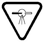
or
(ii) symbol 03-03 in the report of the International Electrotechnical Commission entitled Graphical symbols for electrical equipment in medical practice, Publication 878, 1988, illustrated as follows:

5 All controls, meters, warning lights and other indicators required by this Part must be clearly labelled as to their function.
Construction Standards
General Requirements
6 Diagnostic X-ray equipment must have
(a) if more than one X-ray tube is controlled by one control panel,
(i) a visual indicator on or near each X-ray tube housing that shows that the X-ray tube to which the indicator applies is connected and ready to be energized, and
(ii) a visual indicator on the control panel that shows which of the X-ray tubes are connected and ready to be energized;
(b) a means, appropriate to the rectification type of the equipment, to compensate for variations in X-ray tube voltage caused by line voltage fluctuations;
(c) a visual or audible indicator that warns the operator when the variation in line voltage exceeds the rate set out in subsection 23(2) or a mechanism that, in that event, prevents X-rays from being emitted;
(d) on the control panel
(i) a warning light that indicates when the equipment is ready to be energized,
(ii) a second warning light that indicates when X-rays are being emitted,
(iii) if an automatic exposure control is provided, a visual indicator showing when that mode of operation is selected, and
(iv) if the automatic exposure control mode is not selected or does not exist, controls and visual indicators that enable the operator to select the loading factors before an irradiation;
(e) if the equipment is battery powered, a visual indicator on the control panel showing whether the battery is adequately charged for the proper operation of the equipment;
(f) a mechanism to initiate and terminate an irradiation;
(g) an audible signal to indicate the termination of an irradiation;
(h) in the case of equipment other than mammography equipment, if an X-ray source assembly has a permanent inherent filtration of 0.5 mm aluminum equivalent or less, a means to add additional filtration;
(i) if the equipment moves around a patient by remote control, an emergency stop switch that immediately terminates both the motion of the equipment and the emission of X-rays;
(j) a beam limiting device; and
(k) for equipment that operates within a range set out in column 1 of an item of the table to this paragraph, radiation filters that result in a measured half-value layer of aluminum of not less than
(i) for each X-ray tube voltage set out in column 2 of that item, the half-value layer set out in column 3 of that item, or
(ii) in any other case, the half-value layer obtained by linear interpolation or extrapolation from that table.
TABLE TO PARAGRAPH 6 (k)
Minimum Half-Value Layer of Aluminum
Column 1 Column 2 Column 3 Item Operating Range for Normal Use (kV) X-ray Tube Voltage (kV) Half-value Layer of Aluminum (mm) 1 50 or less (a) 30 0.3 (b) 40 0.4 (c) 50 0.5 2 50 or more but not more than 70 (a) 50 1.2 (b) 60 1.3 (c) 70 1.5 3 70 or more (a) 70 2.1 (b) 80 2.3 (c) 90 2.5 (d) 100 2.7 (e) 110 3.0 (f) 120 3.2 (g) 130 3.5 (h) 140 3.8 (i) 150 4.1
7 (1) An irradiation switch for diagnostic X-ray equipment must
(a) permit the emission of X-rays only when the operator exerts continuous pressure on the switch;
(b) in the case of a foot switch, prevent the emission of any unintended X-rays when it is overturned; and
(c) in the case of mobile equipment, permit the operator to stand at least 3 m from the X-ray source when the X-ray tube is energized.
(2) The controlling timer for diagnostic X-ray equipment must
(a) automatically terminate an irradiation
(i) on completion of a preset irradiation time,
(ii) on attainment of a preset current time product value, or
(iii) on completion of a preset number of X-ray pulses;
(b) permit the operator to terminate an irradiation at any time;
(c) automatically reset itself to its original setting or to zero on termination of an irradiation; and
(d) prevent the initiation of irradiation when the timer is set at zero, at the “off” position or at an unmarked setting.
8 (1) In the case of diagnostic X-ray equipment, other than mammography equipment, when an object set out in column 1 of an item of the table to this subsection is positioned between the patient and the X-ray image receptor, the aluminum equivalent of the object shall not exceed the amount set out in column 2 of that item, as determined using an X-ray beam that
(a) is generated at an X-ray tube voltage of 100 kV;
(b) has a maximum X-ray tube voltage ripple of 10%; and
(c) has a half-value layer of aluminum of 3.7 mm.
TABLE TO SUBSECTION 8(1)
Non-Mammography Equipment — Maximum Aluminum Equivalent of Interpositioned Objects
Column 1 Column 2 Item Object Maximum Aluminum Equivalent (mm) 1 Front panel of cassette holder (total of all layers) 1.2 2 Front panel of film changer (total of all layers) 1.2 3 Cradle 2.3 4 Fixed patient support without an articulated joint 1.2 5 Movable patient support without an articulated joint, including any fixed layers 1.7 6 Patient support with one articulated joint and a radiolucent panel and 1.7 7 Patient support with two or more articulated joints and a radiolucent panel 2.3 8 Cantilevered patient support 2.3 (2) In the case of mammography equipment, when an object set out in column 1 of an item of the table to this subsection is positioned between the patient and the X-ray image receptor, the aluminum equivalent of the object shall not exceed the amount set out in column 2 of that item, as determined using an X-ray beam that
(a) is generated at an X-ray tube voltage of 30 kV;
(b) has a maximum X-ray tube voltage ripple of 10%; and
(c) has a half-value layer of aluminum of 0.3 mm.
TABLE TO SUBSECTION 8(2)
Mammography Equipment — Maximum Aluminum Equivalent of Interpositioned Objects
Column 1 Column 2 Item Object Maximum Aluminum Equivalent (mm) 1 Support table, including all layers 0.3 (3) For the purposes of subsections (1) and (2), any sensor used in automatic exposure control is a part of the X-ray image receptor.
9 For diagnostic X-ray equipment,
(a) the X-ray tube must be securely affixed to and aligned within the X-ray tube housing;
(b) the radiation filters must be securely affixed to the exit port of the X-ray tube housing or beam limiting device, or both; and
(c) the X-ray source assembly must maintain its required position or movement without drift or vibration during operation.
Radiographic Equipment
10 Radiographic equipment that is equipped with an automatic exposure control must have
(a) if the operating X-ray tube voltage is 50 kV or more, a minimum irradiation time capability that does not exceed
(i) in the case of a field emission device that operates in pulse mode, the time equivalent to two pulses, or
(ii) in the case of any other radiographic equipment, the greater of 1/60 s or the time required to deliver a current time product of 5 mAs;
(b) a means to automatically terminate the irradiation when
(i) if the operating X-ray tube voltage is less than 50 kV, the current time product exceeds 1,200 mAs per irradiation, or
(ii) if the operating X-ray tube voltage is 50 kV or more,
(A) the current time product exceeds 600 mAs per irradiation, or
(B) the product of the X-ray tube voltage, X-ray tube current and irradiation time exceeds 60 kVAs per irradiation; and
(c) when an irradiation under automatic exposure control terminates because the limits specified in paragraph (b) have been reached,
(i) a visual indicator or audible signal that warns the operator of the termination, and
(ii) a reset control that must be activated manually before another irradiation under automatic exposure control can be made.
11 (1) General purpose radiographic equipment must have
(a) a beam limiting device that
(i) permits stepless adjustment of the size of the X-ray field, and
(ii) when it is set at the smallest aperture and at a focal spot to image receptor distance of 1 m, has an X-ray field of 5 cm by 5 cm, or less;
(b) an X-ray field indicator that uses light to visually define the X-ray field so that the limits of the X-ray field are visible under the ambient lighting conditions in an X-ray room; and
(c) a means by which the operator may
(i) determine when the X-ray beam axis is perpendicular to the image receptor plane,
(ii) determine the focal spot to image receptor distance to within 2% of that distance, and
(iii) align the centre of the X-ray field with the centre of the image reception area to within 2% of the focal spot to image receptor distance.
(2) The X-ray field indicator referred to in paragraph (1)(b) must
(a) illuminate on average at a minimum of 100 lx when measured from the lesser of
(i) the distance of 1 m from the X-ray source, or
(ii) the maximum focal spot to image receptor distance;
(b) be circumscribed by the beam limiting device;
(c) have as its perimeter the locus of points at which the illumination is one fourth of the maximum illumination in the area; and
(d) when the X-ray beam axis is perpendicular to the image receptor plane, visually define the X-ray field within the following specifications, namely,
(i) the separation between the perimeter of the visually defined field and that of the X-ray field does not exceed 2% of the focal spot to image receptor distance, and
(ii) the dimensions of the X-ray field are indicated and are accurate to within 2% of the focal spot to image receptor distance.
12 (1) General purpose radiographic equipment that has a positive beam limiting system must
(a) permit stepless adjustment of the size of the X-ray field;
(b) when it is set at the smallest aperture and at a focal spot to image receptor distance of 1 m, have an X-ray field of 5 cm by 5 cm, or less;
(c) permit adjustment of the size of the X-ray field to dimensions that are smaller than those of the image reception area;
(d) under the conditions of operation specified in subsection (2),
(i) automatically adjust the dimensions of the X-ray field to the dimensions of the image reception area, or to a selected portion of that area, within 5 s after insertion of the image receptor, or
(ii) prevent the emission of X-rays until the beam limiting device is manually adjusted so that
(A) the dimensions of the X-ray field do not exceed those of the image reception area, or the selected portion of that area, by more than 3% of the focal spot to image receptor distance, and
(B) the sum of the absolute values of the differences in the dimensions of the X-ray field and the image reception area, or the selected portion of that area, does not exceed 4% of the focal spot to image receptor distance; and
(e) automatically revert to one of the requirements set out in paragraph (d) on any change to
(i) the dimensions of the image reception area, or
(ii) the focal spot to image receptor distance, if the change would result in failure to meet the requirements of paragraph (d).
(2) For the purposes of paragraph (1)(d), the conditions of operation are as follows:
(a) the image receptor is inserted into a permanently mounted cassette holder;
(b) neither the length nor the width of the image reception area exceeds 50 cm;
(c) the X-ray beam axis is within 3° of the perpendicular to the image receptor plane;
(d) the X-ray beam axis is within 3° of
(i) the horizontal plane, when the focal spot to image receptor distance is 90 cm or more but not more than 205 cm, or
(ii) the vertical plane, when the focal spot to image receptor distance is 90 cm or more but not more than 130 cm; and
(e) neither tomography nor stereoscopic radiography is being performed.
13 (1) Subject to section 14, radiographic equipment, other than general purpose radiographic or mammography equipment, must have a fixed-aperture beam limiting device that, for the combination of image reception area and focal spot to image receptor distance described in subsection (2),
(a) permits the centre of the X-ray field to be aligned with the centre of the image reception area to within 2% of the focal spot to image receptor distance; and
(b) prevents the X-ray field from extending beyond any edge of the image reception area.
(2) The fixed-aperture beam limiting device referred to in subsection (1) must display on its exterior surface a specified focal spot to image receptor distance and the dimensions of its image reception area at that distance.
14 Mobile radiographic equipment that does not meet the requirements of section 13 must have
(a) a beam limiting device that
(i) permits stepless adjustment of the size of the X-ray field, and
(ii) when it is set at the smallest aperture and at a focal spot to image receptor distance of 1 m, has an X-ray field of 5 cm by 5 cm, or less;
(b) an X-ray field indicator referred to in paragraph 11(1)(b) that, when the X-ray beam axis is perpendicular to the image receptor plane, permits the alignment of the edges of the illuminated field with the edges of the X-ray field so that the difference between their edges does not exceed 2% of the focal spot to image receptor distance; and
(c) a means to determine the focal spot to image receptor distance to an accuracy of 2% or less of that distance.
15 (1) Mammography equipment must have
(a) a beam limiting device that limits the size of the X-ray beam to prevent the X-ray field, at any focal spot to image receptor distance at which the equipment operates, from extending
(i) more than 5 mm beyond the edge of the patient support next to the chest wall of the patient, and
(ii) more than a distance equivalent to 2% of the focal spot to image receptor distance beyond any other edge of the image reception area;
(b) an image receptor supporting device that
(i) has protective shielding that limits the residual radiation in accordance with section 26,
(ii) extends to the patient’s chest wall, and
(iii) at every other edge, extends beyond the X-ray field by at least 1% of the focal spot to image receptor distance; and
(c) a breast compression device that
(i) is foot-actuated to start the compression,
(ii) permits fine adjustment of motion during the compression,
(iii) permits rapid decompression,
(iv) has motion adjustment controls on both sides of the position for the patient, and
(v) allows the portion of the compression plate in contact with the breast to be brought to within 10 mm of the surface of the patient support.
(2) Mammography equipment that has a removable, fixed-aperture beam limiting device must display the following information on its external surface:
(a) the dimensions of the image reception area; and
(b) the focal spot to image receptor distance at which the beam limiting device must be used.
16 Diagnostic X-ray equipment that has a spotfilm device must have
(a) if the angle of the image receptor plane or of the X-ray source assembly is adjustable by the operator, a means to indicate when the X-ray beam axis is perpendicular to the image receptor plane;
(b) when the X-ray beam axis is perpendicular to the image receptor plane, a mechanism that
(i) when the X-ray field is larger than the selected portion of the image reception area, adjusts the dimensions of the field automatically to those of the selected portion of that area,
(ii) when the X-ray field is smaller than the selected portion of the image reception area, permits the adjustment of the dimensions of the X-ray field,
(iii) permits the perimeter of the X-ray field to be aligned with that of the selected portion of the image reception area so that
(A) the dimensions of the X-ray field differ from the corresponding dimensions of the image reception area by a distance that does not exceed 3% of the focal spot to image receptor distance, and
(B) the sum of the absolute values of the differences in the dimensions between the X-ray field size and the image reception area does not exceed 4% of the focal spot to image receptor distance, and
(iv) permits the centre of the X-ray field to be aligned with the centre of the selected portion of the image reception area to within 2% of the focal spot to image receptor distance;
(c) a mechanism for adjusting the X-ray field to dimensions that are smaller than those of the selected portion of the image reception area so that
(i) when the mechanism is set at the smallest aperture and at the longest focal spot to image receptor distance, the X-ray field is 5 cm by 5 cm, or less, and
(ii) the requirement set out in subparagraph (b)(iv) is met when the X-ray beam axis is perpendicular to the image receptor plane; and
(d) if a means is provided for the operator to override a failure of the automatic X-ray field size adjustment, a visual indicator at the operator’s position that shows when the override is activated.
17 Radiographic equipment, other than equipment described in sections 11 to 16, must have a beam limiting device that, when the axis of the X-ray beam is perpendicular to the image receptor plane, permits
(a) the alignment of the centre of the X-ray field with the centre of the image reception area to within 2% of the focal spot to image receptor distance; and
(b) the adjustment of the perimeter of the X-ray field so that the perimeter does not extend beyond that of the image reception area by more than 2% of the focal spot to image receptor distance.
Radioscopic Equipment
18 Radioscopic equipment must
(a) have an X-ray image intensifier that includes protective shielding that
(i) for any focal spot to image receptor distance, intercepts the entire cross section of the X-ray beam,
(ii) intercepts the X-ray beam and scattered radiation from the image intensifier that would otherwise reach the operator,
(iii) prevents the radioscopic X-ray tube from emitting X-rays unless the protective shielding is in place to intercept the X-ray beam, and
(iv) sufficiently attenuates the X-rays transmitted through or scattered from the entrance window of the radioscopic imaging assembly to meet the requirements of section 32;
(b) for mobile radioscopic equipment, have an X-ray image intensifier that is an integral part of the equipment or is interlocked in such a manner that its removal prevents X-rays from being produced;
(c) for stationary radioscopic equipment, prevent the X-ray tube from producing X-rays when there is no image receptor in place to intercept the X-ray beam;
(d) for stationary radioscopic equipment that is not equipped with remote control,
(i) have protective shielding of at least 0.25 mm lead equivalent at 100 kV, such as overlapping hinged or sliding panels or protective drapes, to intercept the scattered radiation that would otherwise reach the operator, and
(ii) the capability to remove the protective shielding referred to in subparagraph (i) when it interferes with the performance of diagnostic procedures;
(e) have an irradiation switch that
(i) requires continuous pressure by the operator for the entire period of an irradiation, and
(ii) enables the operator to terminate the recording of serial radioscopic images at any time;
(f) have a chronometer that
(i) indicates the amount of time that the equipment has been emitting X-rays, and
(ii) can be reset to zero or any other selected value;
(g) have a positive beam limiting system that, when the X-ray beam axis is perpendicular to the image receptor plane, permits the alignment of the perimeter of the illuminated field with that of the X-ray field so that
(i) the difference between the perimeters does not exceed a distance equivalent to 3% of the focal spot to image receptor distance, and
(ii) the sum of the excess length and excess width does not exceed 4% of the focal spot to image receptor distance;
(h) have visual indicators that continuously display the X-ray tube voltage and the X-ray tube current; and
(i) have a device that limits the minimum focal spot to skin distance
(i) for mobile radioscopic equipment, to 30 cm,
(ii) for stationary radioscopic equipment, to 38 cm,
(iii) for radioscopic equipment fitted with an X-ray image intensifier and used for special applications that require shorter focal spot to skin distances than the focal spot to skin distances specified in subparagraphs (i) and (ii), to 20 cm, or
(iv) for small-format, low-intensity radioscopic equipment, to the distance at which the equipment delivers an air kerma rate of 50 mGy/min or an exposure rate of 5.75 R/min.
19 Radioscopic equipment that is used for cineradiography must have visual indicators that continuously display the X-ray tube voltage and the X-ray tube current.
20 A high-level irradiation control for radioscopic equipment must
(a) be activated by a separate means that requires continuous pressure by the operator for it to emit X-rays; and
(b) when it is in use, emit a continuous audible signal or an intermittent signal with silent periods of no longer than one second.
Functioning Standards
21 Diagnostic X-ray equipment must function in accordance with the requirements set out in sections 22 to 32 during its operation under normal conditions of use.
22 (1) The definitions in this subsection apply in this section.
- coefficient of variation
coefficient of variation means the ratio of the estimated standard deviation to the mean value of a series of measurements calculated using the equation:
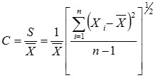
where
- C
- is the coefficient of variation;
- S
- is the estimated standard deviation;
- Xi
- is the value of the ith measurement;
- is the mean value of the measurements; and
- n
- is the number of measurements. (coefficient de variation)
- exposure to the X-ray image receptor
exposure to the X-ray image receptor means the amount of X-rays, registered by one or more detectors located in a fixed position in proximity to the X-ray image receptor, that is necessary to produce a radiogram of the overall density sought by the operator. (exposition au récepteur d’image radiologique)
(2) For any combination of X-ray tube voltage, X-ray tube current and irradiation time, or for any selected exposure to the X-ray image receptor, when the line voltage for each measurement is accurate to within 1% of the mean line voltage value of all the measurements, and when all variable controls for the loading factors are adjusted to alternate settings and reset to the test setting before each measurement,
(a) the coefficient of variation of any 10 consecutive air kerma or exposure measurements, taken at the same point along the X-ray beam axis within a period of one hour, must be no greater than 0.05; and
(b) each of the 10 air kerma or exposure measurements taken under paragraph (a) must be within 15% of the mean value of those measurements.
(3) For the purposes of subsection (2), diagnostic X-ray equipment with an automatic exposure control must have attenuating material in the X-ray beam that is thick enough that the loading factors can be adjusted to provide single irradiations of at least
(a) 12 pulses, in the case of a field emission device that operates in pulse mode; or
(b) 0.1 s, in the case of any other diagnostic X-ray equipment.
23 (1) This section applies in respect of diagnostic X-ray equipment that has
(a) a high-voltage generator that is not a stored energy high-voltage generator;
(b) loading factors that do not change automatically to compensate for unintentional variations in X-ray tube voltage; and
(c) an irradiation time of at least 0.1 s and a current time product of at least 5 mAs.
(2) In the case of a line voltage regulation of 6% or less, the loading factor set out in column 1 of an item of the table to this subsection must not deviate from the selected value, for any combination of loading factors, by more than the quantity set out in column 2 of that item.
TABLE TO SUBSECTION 23(2)
Maximum Deviation of Loading Factors
Column 1 Column 2 Item Loading Factor Maximum Deviation from the Selected Value 1 X-ray tube voltage of mammography equipment 5% 2 X-ray tube voltage of non-mammography equipment 10% 3 Irradiation time 10% plus 1 ms 4 X-ray tube current 20% 5 Current time product 10% plus 0.2 mAs
24 (1) The controlling timer or automatic exposure control device of diagnostic X-ray equipment must have a minimum irradiation time capability that does not exceed the greater of:
(a) 1/60 s, or
(b) the time required to deliver a current time product of 5 mAs.
(2) If the automatic exposure control of diagnostic X-ray equipment is selected, the variation in optical density set out in subsection (3) or (4) must be determined using objects that are made of human-tissue equivalent material and have thicknesses that are representative of the actual range of the body thicknesses of the patients.
(3) The automatic exposure control device of diagnostic X-ray equipment, other than mammography equipment, when the X-ray tube voltage and the thickness of the objects described in subsection (2) are held constant or varied as specified in columns 1 and 2 of an item of the table to this subsection, must limit the variation in optical density of the resulting radiograms to the quantity set out in column 3 of that item.
TABLE TO SUBSECTION 24(3)
Maximum Variation in Optical Density
Column 1 Column 2 Column 3 Item X-ray Tube Voltage Thickness of the Object Maximum Variation in Optical Density 1 Variable Constant 0.15 2 Constant Variable 0.20 3 Variable Variable 0.20 4 Constant Constant 0.10 (4) The automatic exposure control device of mammography equipment, when both the X-ray tube voltage and the thickness of the objects described in subsection (2) are varied, must limit the variation in optical density of the resulting radiograms to 0.15.
25 (1) For any selected value of X-ray tube voltage within a range determined in accordance with subsection (2), the quotients of the average air kerma or exposure measurement divided by the indicated current time product, obtained at the applicable settings specified in subsection (3), must not differ by more than 0.10 times their sum as determined by the formula
|X1 - X2| ≤ 0,1 (X1 + X2)
where
- X1
- is the quotient of the average air kerma or exposure
- X2
- is the quotient of the average air kerma or exposure measurement divided by the current time product determined at the second of the two applicable settings specified in subsection (3).
(2) The range referred to in subsection (1) is the smaller of
(a) 40% to 90% of the maximum available X-ray tube voltage, or
(b) the range of X-ray tube voltages specified for the diagnostic X-ray equipment by the manufacturer.
(3) The quotients referred to in subsection (1) must be determined at
(a) if the X-ray tube current is selected in discrete steps, any two consecutive X-ray tube current settings;
(b) if the X-ray tube current selection is continuous, any two X-ray tube current settings that differ by a factor of 2 or less;
(c) if the current time product is selected in discrete steps, any two consecutive current time product settings; or
(d) if the current time product selection is continuous, any two current time product settings that differ by a factor of 2 or less.
(4) If diagnostic X-ray equipment has more than one focal spot, the quotients referred to in subsection (1) must be determined for all combinations of two focal spots that have a nominal focal spot size greater than 0.45 mm, and all combinations of two focal spots that have a nominal focal spot size equal to or less than 0.45 mm at the applicable settings set out in subsection (3).
26 (1) For mammography equipment, the residual radiation behind the image receptor supporting device must not exceed an air kerma measurement of 1.0 µGy or an exposure measurement of 0.115 mR per irradiation when the equipment is operated at
(a) its maximum X-ray field and minimum focal spot to image receptor distance; and
(b) its maximum X-ray tube voltage and maximum current time product.
(2) For the purposes of subsection (1), the air kerma or exposure measurement must be averaged over a detection area that is 100 cm2, of which no linear dimension is greater than 20 cm, centred at 5 cm from any accessible surface beyond the image receptor supporting device.
27 (1) Mammography equipment must have a minimum rate of radiation output of 7.0 mGy/s or 802 mR/s when the equipment is operated
(a) with a molybdenum anode and molybdenum filter;
(b) with the breast compression device in place between the X-ray source and the detector; and
(c) at an X-ray tube voltage of 28 kV in standard mammography mode at any focal spot to image receptor distance.
(2) For the purposes of subsection (1), the minimum rate of radiation output must be
(a) measured at a position that is 4.5 cm above the patient support; and
(b) averaged over a period of irradiation of 3.0 s.
28 (1) Radioscopic equipment that has a feature described in column 1 of an item of the table to this subsection, other than when radioscopic images are being recorded, must not operate at any combination of X-ray tube voltage and X-ray tube current that results in an air kerma rate that exceeds that set out in column 2 of that item or an exposure rate that exceeds that set out in column 3 of that item:
TABLE TO SUBSECTION 28(1)
Maximum Air Kerma or Exposure Rate of Radioscopic Equipment, Other Than When It Is Recording Images
Column 1 Column 2 Column 3 Item Feature Maximum Air Kerma Rate Maximum Exposure Rate 1 Not equipped with an automatic intensity control 50 mGy/min 5.75 R/min 2 Equipped with an automatic intensity control 100 mGy/min 11.5 R/min 3 Equipped with both an automatic intensity control and a high-level irradiation control when the latter is activated 150 mGy/min 17.25 R/min (2) For the purposes of subsection (1), the air kerma or exposure rate must be determined at a location along the X-ray beam axis that is
(a) if the X-ray source is below the table, 1 cm above the table;
(b) if the X-ray source is above the table, 30 cm above the table and with the X-ray source assembly positioned as closely as possible to the location of the measurement;
(c) if the equipment is a C-arm radioscope, 30 cm from the input surface of the radioscopic imaging assembly; or
(d) if the equipment is a lateral type radioscope, 15 cm from the centre line of the table in the direction of the X-ray source and with the X-ray source assembly positioned as closely as possible to the location of the measurement for all positions of the table.
29 (1) The leakage radiation from the X-ray source assembly of diagnostic X-ray equipment must not exceed an air kerma rate of 1.0 mGy/h or an exposure rate of 115 mR/h when the equipment is operated at the nominal X-ray tube conditions of loading that correspond to the maximum specified energy input in one hour.
(2) For the purposes of subsection (1), the rate must be averaged over a detection area of 100 cm2, of which no linear dimension is greater than 20 cm, that is centred at 1 m from the focal point.
30 (1) If high voltage can appear across the X-ray tube of the diagnostic X-ray equipment, then the radiation emitting from the X-ray source assembly of the equipment must not exceed an air kerma rate of 20.0 µGy/h or an exposure rate of 2.3 mR/h when
(a) the equipment is operated with its beam limiting device fully open; and
(b) the automatic exposure control or the irradiation switch has not been activated.
(2) For the purposes of subsection (1), the rate must be averaged over a detection area of 10 cm2, of which no linear dimension is greater than 5 cm, that is centred at 5 cm from any accessible surface of the X-ray source assembly.
31 (1) Under any operating condition, the radiation from any component of diagnostic X-ray equipment, other than the X-ray source assembly, must not exceed an air kerma rate of 20.0 µGy/h or an exposure rate of 2.3 mR/h.
(2) For the purposes of subsection 1, the rate must be averaged over a detection area of 10 cm2, of which no linear dimension is greater than 5 cm, that is centred at 5 cm from any accessible surface of the component.
32 (1) In the case of radioscopic equipment, the radiation resulting from the transmission of the X-ray beam through, or scattered from, the entrance window of the radioscopic imaging assembly must not exceed an air kerma rate of 2 mGy/h for an entrance air kerma rate of 1 Gy/min or an exposure rate of 2 mR/h for an entrance exposure rate of 1 R/min.
(2) For the purposes of subsection (1), the rate must be
(a) taken at the applicable location specified in subsection 28(2) for the type or configuration of the equipment;
(b) taken with an attenuation block made of aluminum and having the dimensions 20 cm by 20 cm by 3.8 cm that is positioned between the point of entrance of the radiation and the image reception area of the radioscopic imaging assembly; and
(c) averaged over a detection area of 100 cm 2 that is centred 10 cm from any accessible surface of the radioscopic imaging assembly and in a plane beyond the image receptor.
PART XIIIUltrasound Therapy Devices
Interpretation
1 In this Part and in item 13 of Schedule I,
- amplitude modulated wave
amplitude modulated wave means a wave in which the ratio of the temporal maximum pressure amplitude to the root-mean square pressure amplitude, each spatially averaged over the effective radiating surface, is greater than 1.05; (onde modulée en amplitude)
- applicator
applicator means the part of the ultrasound therapy device designed to transmit ultrasonic power from the transducer to a patient and includes the transducer and any associated housing; (applicateur)
- continuous wave
continuous wave means a wave in which the ratio of the temporal maximum pressure amplitude to the root-mean square pressure amplitude, each spatially averaged over the effective radiating surface, is less than or equal to 1.05; (onde entretenue)
- control panel
control panel means that portion of the external surface of the housing on which the user controls are mounted; (tableau de commande)
- effective intensity
effective intensity[Revoked, SOR/84-930, s. 2]
- effective radiating area
effective radiating area means the area of the effective radiating surface that encompasses all points at which the ultrasonic intensity is equal to or greater than five per cent of the maximum spatial ultrasonic intensity at the effective radiating surface, expressed in square centimetres (cm2); (aire émettrice utile)
- effective radiating surface
effective radiating surface means the surface covering all points that are 5 mm from the applicator face; (surface émettrice utile)
- effective ultrasonic intensity
effective ultrasonic intensity, with respect to ultrasonic power, means
(a) in the case of a focussing applicator, the quotient obtained by dividing the amount of the ultrasonic power by the amount of the focal area, and
(b) in any other case, the quotient obtained by dividing the amount of the ultrasonic power by the amount of the effective radiating area; (intensité ultrasonore utile)
- focal area
focal area means the area of the focal surface expressed in square centimetres (cm2); (aire focale)
- focal length
focal length in respect of a focussing applicator, means the distance in centimetres between
(a) that point of the effective radiating surface the coordinates of which are the mean values of the coordinates of the points of that surface, and
(b) that point of the focal surface the coordinates of which are the mean values of the coordinates of the points of that surface; (longueur focale)
- focal surface
focal surface in respect of a focussing applicator, means the beam cross-section with the smallest area; (surface focale)
- focussing applicator
focussing applicator means an applicator in which the quotient of the area of the surface having the smallest area, in any plane consisting of the points at which the ultrasonic intensity is greater than five per cent of the maximum intensity in that plane, and the effective radiating area is less than one-half; (applicateur focalisant)
- housing
housing means a structure that encloses
(a) that portion of a fully assembled ultrasound therapy device that supplies the electrical energy to the applicator, and
(b) the electrical circuitry of the device; (logement)
- maximum intensity
maximum intensity[Revoked, SOR/84-930, s. 2]
- pressure amplitude
pressure amplitude means the instantaneous value of the modulating waveform in the following equation:
p(t)=p1(t)p2(t)
where
- p(t)
- is the instantaneous pressure,
- p1(t)
- is the modulating wave form,
- p2(t)
- is the relative amplitude of the carrier wave normalized to a peak height of one,
- p(t), p1(t) and p2(t)
- are periodic functions of time, t, at any point in space, and
- the period of p1(t)
- is greater than the period p2(t);
(amplitude de pression)
- pulse duration
pulse duration means a time interval, expressed in seconds, beginning at the first time the pressure amplitude exceeds the value that equals the sum of the minimum pressure amplitude and 10 per cent of the difference between the maximum and minimum pressure amplitudes and ending at the last time the pressure amplitude returns to that value; (durée des impulsions)
- pulse repetition rate
pulse repetition rate means the repetition frequency of the wave shape that modulates the ultrasonic radiation carrier wave expressed in pulses per second (pps); (taux de répétition des impulsions)
- service controls
service controls means controls provided by the manufacturer for adjusting the ultrasound therapy device that, under normal conditions of use, are not accessible to the user; (commandes internes)
- transducer
transducer[Revoked, SOR/84-930, s. 2]
- ultrasonic frequency
ultrasonic frequency means the frequency of the ultrasonic power wave, expressed in kilohertz (kHz) or megahertz (mHz); (fréquence)
- ultrasonic power
ultrasonic power means the total power that is emitted in the form of ultrasonic radiation by the applicator and that is averaged over each cycle of the ultrasonic radiation carrier wave, expressed in watts (W); (puissance acoustique)
- user controls
user controls means controls provided by the manufacturer for operating the ultrasound therapy device that, under normal conditions of use, are accessible to the user. (commandes externes)
Standards of Design and Construction
2 (1) Every ultrasound therapy device shall be designed and constructed in such a manner that, under the conditions of use specified by the manufacturer, it functions in accordance with section 3 for as long as the device has its original components or replacement components recommended by the manufacturer.
(2) Every ultrasound therapy device shall be designed in such a manner that
(a) all marks, labels and signs are permanently affixed thereon and clearly visible; and
(b) all user controls, meters, lights or other indicators are clearly visible, readily discernible and clearly labelled to indicate their function.
(3) Every ultrasound therapy device shall bear
(a) on the external surface of its housing
(i) the name and address of the manufacturer,
(ii) the name and address of the distributor, if the distributor is not the manufacturer,
(iii) the type and model designation,
(iv) the serial number,
(v) the month and year of manufacture,
(vi) the ultrasonic frequencies in kilohertz (kHz) or megahertz (mHz),
(vii) a statement indicating whether the wave produced by the device is a continuous wave or an amplitude modulated wave,
(viii) in the case of a device that produces an amplitude modulated wave,
(A) the pulse repetition rate, the pulse duration, the ratio of the temporal maximum effective ultrasonic intensity to the temporal average effective ultrasonic intensity, and a description of the wave shape, where these parameters do not vary depending on the power, and
(B) the pulse repetition rate, the pulse duration, the ratio of the temporal maximum effective ultrasonic intensity to the temporal average effective ultrasonic intensity, and a description of the wave shape, all at temporal maximum ultrasonic power where these parameters do vary depending on the power,
(ix) the line voltage used for normal operation, and
(x) the ultrasound radiation warning sign described in section 4; and
(xi) to (xiii) [Revoked, SOR/84-930, s. 3]
(b) on the external surface of each applicator
(i) the identification of the type and model of the ultrasound therapy device for which it is designed,
(ii) where an applicator is a focussing applicator, the focal length and the focal area,
(iii) a unique serial number or other unique identification, and
(iv) the effective radiating area in square centimetres (cm2).
(4) Every ultrasound therapy device shall be designed and constructed to include the following safety features:
(a) on the control panel, separate indicator lights or other equivalent indicators that have an expected lifetime of at least 5000 hours,
(i) to show when the line voltage is “ON” or “OFF”, and
(ii) to show when the ultrasonic power is being applied to the applicator;
(b) a power indicator that
(i) in the case of a device that produces a continuous wave, shows by a direct reading the level of the temporal average ultrasonic power and the temporal average effective ultrasonic intensity,
(ii) in the case of a device that produces an amplitude modulated wave, shows by a direct reading the level of the temporal maximum ultrasonic power and the temporal maximum effective ultrasonic intensity, and
(iii) functions in accordance with section 3;
(c) a clear and reliable indicator of the range used, if the power indicator described in paragraph (b) utilizes two or more different ranges of measurement; and
(d) a timer that
(i) terminates the generation of ultrasound after a preset time interval and then returns to zero,
(ii) does not allow the generation of ultrasound with the timer set at zero,
(iii) is adjustable to settings in increments not greater than one minute, and
(iv) functions in accordance with section 3.
(5) Where an ultrasound therapy device is equipped with an ultrasonic power control, that control shall
(a) allow the adjustment of ultrasonic power;
(b) have a minimum and maximum adjustment that directly relates to the ultrasonic power level indicator; and
(c) function in accordance with section 3.
Standards of Functioning
3 (1) Every ultrasound therapy device shall function in such a manner that when the device is operating with its user controls adjusted to yield the maximum temporal average-spatial average effective ultrasonic intensity, such intensity shall not exceed 3 W/cm2, when measured in accordance with subsection (2).
(2) The method used to measure the effective ultrasonic intensity for the purposes of subsection (1) shall produce a result that is at least as accurate as the result that would be produced by using
(a) an ultrasound balance radiometer to measure the ultrasonic power; and
(b) an ultrasound detector of dimensions less than one wavelength in water to measure the pulse repetition rate, the pulse duration and the effective radiating area.
(3) The power indicator referred to in paragraph 2(4)(b) shall show on the scale of the ultrasonic power control or on the output power meter the ultrasonic power with an accuracy of ±20 per cent when the output is greater than 10 per cent of the maximum ultrasonic power.
(4) The timer referred to in paragraph 2(4)(d) shall be accurate to within 30 seconds for settings less than five minutes, to within 10 per cent for settings from five to 10 minutes, and to within one minute for settings greater than 10 minutes.
(5) The ultrasonic power output shall remain constant within ±20 per cent of its initial value during one hour of continuous operation, at maximum output and at rated supply line voltage, in water at a temperature of 22°C ± 3°C.
(6) The actual ultrasonic frequency of an ultrasound therapy device shall not differ more than ±5% from the ultrasonic frequency of the device that is stated on the external surface of the housing of the device pursuant to subparagraph 2(3)(a)(vi).
(7) The effective radiating area shall be kept within ±20 per cent of the rated value given by the manufacturer.
Warning Sign Specifications
4 The warning sign referred to in subparagraph 2(3)(a)(x) is a sign that
(a) is shown in two contrasting colours;
(b) is clearly visible and identifiable from a distance of 1 m;
(c) has no outer dimensions less than 2 cm;
(d) bears the words “CAUTION-ULTRASOUND, ATTENTION-ULTRASONS”; and
(e) is designed in accordance with the following diagram:

PART XIVAnalytical X-ray Equipment
Interpretation
1 The definitions in this section apply in this Part.
- accessory
accessory means any component used on analytical X-ray equipment in order to enable the equipment to perform its intended use, to adapt the equipment to some special purpose, to facilitate use of the equipment, to enhance the performance of the equipment or to enable the function of the equipment to be integrated with that of other equipment. (accessoire)
- beam-limiting device
beam-limiting device means a device that limits the dimensions of a radiation beam. (dispositif de limitation du faisceau)
- control panel
control panel means that part of analytical X-ray equipment on which are mounted
(a) one or more manually-operated controls that regulate all, or some, of the functions of the equipment; and
(b) meters, lights or other indicators that disclose operating factors and conditions. (poste de commande)
- high-voltage generator
high-voltage generator means a combination of the components necessary for the production and control of the electrical energy to be supplied to an X-ray tube, which components usually consist of a high-voltage transformer assembly and a control assembly. (générateur radiologique)
- interlock
interlock means a system that prevents the start or the continued operation of equipment unless certain predetermined conditions prevail. (verrouillage)
- protective shielding
protective shielding means material that limits the extent of a radiation beam or attenuates stray radiation. (barrière de protection radiologique)
- radiation aperture
radiation aperture means an aperture in the protective shielding of a radiation source or a beam-limiting device, that is intended to give passage to the radiation beam. (fenêtre)
- radiation beam
radiation beam means a spatial region that is limited in solid angle and that contains a flux of ionizing radiation which originates from a radiation source that is considered a point source. (faisceau de rayonnement)
- shutter
shutter means a mechanism that opens or closes a radiation aperture to enable or prevent the passage of a radiation beam. (obturateur)
- stray radiation
stray radiation means all ionizing radiation except that of the specified radiation beam under consideration, but includes that part of the radiation beam which emerges from the material being irradiated. (rayonnement parasite)
- timing device
timing device means a device that
(a) integrates or presents the time elapsed during an equipment function; and
(b) changes the state of operation at the end of a predetermined time interval. (intégrateur de temps)
Standards of Design and Construction
2 Analytical X-ray equipment shall be designed and constructed in such a manner that, when installed, operated and maintained in accordance with the instructions referred to in paragraph 3(a), it functions in accordance with section 10.
3 Analytical X-ray equipment shall be accompanied by
(a) instructions from the manufacturer as to the installation, interconnection, testing, operation and maintenance of the equipment and its accessories and replacement components; and
(b) information from the manufacturer on the recommended accessories and replacement components.
4 Analytical X-ray equipment shall bear on the control panel, next to any one switch that turns on an X-ray tube, each of the following labels:
(a) a label bearing an X-radiation warning symbol that
(i) is displayed in two contrasting colours,
(ii) is clearly visible and readily discernible from a distance of 1 m,
(iii) has no outer dimension that is less than 2 cm,
(iv) bears the words “CAUTION: X-RADIATION — ATTENTION : RAYONNEMENTS X”, and
(v) conforms to the following diagram, namely,
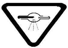
(b) a label bearing the words
“CAUTION — X-RADIATION. This Equipment Produces High Intensity X-radiation When Energized. To be Operated Only by Qualified Personnel.
ATTENTION — RAYONNEMENTS X. Cet appareil produit des rayonnements X haute intensité lorsqu’il est sous tension. Son utilisation est réservée au personnel compétent;” and
(c) a label setting out
(i) the name and address of the manufacturer,
(ii) the model designation,
(iii) the serial number,
(iv) the date of manufacture, and
(v) the country of manufacture.
5 Analytical X-ray equipment shall be designed and constructed in such a manner that
(a) all labels required by this Part are securely affixed to the equipment and clearly visible;
(b) all controls, meters, lights and other indicators required by this Part are readily discernible and clearly labelled as to function;
(c) the X-ray tube housing, shutters, beam-limiting devices, couplings and protective shielding will not deform or their shielding properties deteriorate;
(d) when the equipment is assembled, the radiation beam is contained within protective shielding that is equipped with an interlock; and
(e) where a radiation aperture must be open in order to set up or align the equipment, a visual and an aural indicator warns the operator that the radiation aperture is open for the duration that it is open.
6 Analytical X-ray equipment shall be designed and constructed to include
(a) a control panel that regulates one or more X-ray tubes and that includes
(i) an “ON/OFF” switch equipped with warning lights that indicate when the control panel is energized,
(ii) a key-actuated control that prevents X-radiation production with the key removed,
(iii) an “ON/OFF” X-radiation switch for each X-ray tube, equipped with a warning light that indicates when X-radiation is being produced,
(iv) indicators or meters that identify which X-ray tube is being used and the corresponding applied X-ray tube voltage and X-ray tube current, unless this information is provided on an accessory,
(v) a warning light for each X-ray tube that indicates when any shutter on that tube is open, and
(vi) a timing device for each X-ray tube, unless the device is a component of an accessory;
(b) for each radiation aperture, a shutter that
(i) remains closed when not in use,
(ii) requires the operator to open it manually or by means of a computer controlled function,
(iii) is equipped with an interlock in its operating mechanism, unless an alignment device or accessory is integrated into the radiation aperture and that alignment device or accessory is equipped with an interlock,
(iv) can be removed only with special tools, and
(v) is designed with protective shielding;
(c) labyrinth-type joints, couplings or interfaces between radiation apertures, shutters, protective shielding, beam-limiting devices and accessories; and
(d) where the equipment is designed for use with interchangeable filters,
(i) interlocks or other means to ensure that insertion or removal of those filters is possible only when X-radiation is not being produced, and
(ii) filter slots that are covered by protective shielding when they are not in use.
7 Every accessory supplied by a manufacturer shall be accompanied by information that
(a) sets out the specific analytical X-ray equipment for which the accessory is designed; and
(b) indicates the design and specifications of the couplings, fittings, interfaces and parts that are necessary for the installation and functioning of that accessory.
8 Every accessory associated with the production, collimation, transmission or detection of X-radiation shall bear on its external surface a label that sets out, in respect of that accessory,
(a) the name and address of the manufacturer;
(b) the model designation;
(c) the serial number;
(d) the date of manufacture; and
(e) the country of manufacture.
9 Every accessory associated with the production, collimation, transmission or detection of X-radiation shall be designed and constructed in such a manner that it is contained within protective shielding that
(a) prevents the radiation beam from touching any part of the operator’s body; and
(b) is equipped with an interlock.
Standards of Functioning
10 Assembled analytical X-ray equipment, when operated at any of its designed X-ray tube voltage and X-ray tube current specifications, shall function in such a way that the X-radiation emitted does not exceed 0.5 milliroentgen (≈4.38 microgray air kerma) in one hour at a distance of 5 cm from
(a) any accessible external surfaces of any X-ray tube housing, beam-limiting device, protective shielding or accessory;
(b) any radiation aperture, shutter or filter slot that is in the closed position; and
(c) any point on the housing of the high-voltage generator.
PART XVCabinet X-ray Equipment
Interpretation
1 In this Part,
- cabinet
cabinet means an enclosure that, independent of existing structures, contains the X-ray generator, detectors and space for the material to be examined, provides radiation attenuation and prevents access to the X-ray beam; (enceinte)
- central processing unit
central processing unit means that part of the electronic circuitry that receives signals from the X-ray detection system and subsequently causes an action to be taken on the material being examined; (unité centrale)
- control panel
control panel means the control panel referred to in paragraph 7(a) of this Part; (tableau de commande)
- detector
detector means the image receptor or other device that intereacts with the X-rays to produce a signal corresponding to the intensity of the X-rays incident on it; (détecteur)
- material
material means any substance, object or product subjected to X-ray irradiation for the purpose of obtaining information about that substance, object or product; (matière)
- model designation
model designation means any combination of letters or figures or both letters and figures by which a device that bears that designation is identified as having characteristics and design features that are uniform; (désignation du modèle)
- primary X-ray beam
primary X-ray beam means that X-radiation emitted directly from the target of the X-ray tube and emerging from the port of the X-ray tube housing; (faisceau primaire de rayons X)
- X-ray generator
X-ray generator means an assembly of components, including an X-ray tube and its housing and shielding, designed and constructed for the controlled generation of X-rays. (producteur de rayons X)
Standards of Design and Construction
2 Cabinet X-ray equipment shall be designed and constructed in such a manner that, when installed and maintained in accordance with the instructions referred to in section 3, it functions within the standards of functioning described in section 10 for as long as the device has its original components or has replacement components recommended by the manufacturer.
3 Cabinet X-ray equipment shall be equipped with installation and maintenance instructions furnished by the manufacturer of the device that, if followed, will enable the device to function within the requirements of this Part.
4 Cabinet X-ray equipment shall bear
(a) on the external surface of the X-ray control panel,
(i) a warning sign, next to the X-rays “ON” switch, that
(A) indicates the possibility of hazardous radiation emission when the device is in operation, and
(B) prohibits unauthorized use,
(ii) the X-radiation warning sign described in section 11, and
(iii) a permanent mark or label that sets out, in respect of the device,
(A) the name of the manufacturer,
(B) the model designation,
(C) the serial number,
(D) the date of manufacture, and
(E) the city and country of manufacture; and
(b) on the external surface of all doors or panels through which material to be X-rayed is inserted into or removed from the device, the X-radiation warning sign described in section 11.
5 Cabinet X-ray equipment shall be designed and constructed in such a manner that
(a) all marks, labels and signs required by this Part are securely affixed to the device and are clearly visible and readily discernible; and
(b) all controls, meters, lights or other indicators required by this Part are readily discernible and clearly labelled or marked with respect to function.
6 Cabinet X-ray equipment shall have sufficient shielding to enable the device to function within the standards of functioning described in section 10.
7 Cabinet X-ray equipment shall be designed and constructed to include the following:
(a) a control panel having the following safety features:
(i) a power “ON/OFF” switch,
(ii) a lock of a type that requires the insertion of a key before X-rays can be produced and the removal of the key to terminate production of X-rays,
(iii) a warning light that indicates when the power is “ON”,
(iv) a warning light, in addition to the warning light referred to in subparagraph (iii), that
(A) indicates when X-rays are being generated,
(B) where the device is designed to operate with a pulsed X-ray beam, is activated for at least one-half second, and
(C) unless there is a warning light or other indicator referred to in subparagraph (v) incorporated on the control panel, is connected and interlocked in such a manner that X-rays cannot be produced if the warning light malfunctions, and
(v) unless the warning light referred to in subparagraph (iv) is connected and interlocked in the manner described in clause (iv)(C), a warning light or other indicator that duplicates the functions of the warning light referred to in subparagraph (iv) whose function is not affected if the warning light referred to in that subparagraph malfunctions;
(b) shielded doors or panels over all access openings designed for insertion or removal of any material to be examined except where the design of the device prevents the insertion of any part of the human body into the primary X-ray beam;
(c) safety features connecting and interlocking each of the doors and panels referred to in paragraph (b) with at least two independent interlocks to prevent the generation of X-rays if any door or panel is open;
(d) interlocks on all doors and panels, other than those doors and panels referred to in paragraph (b), that allow access to areas inside the cabinet where the exposure rate to X-rays may exceed 0.5 milliroentgen per hour to prevent the generation of X-rays if any door or panel is opened or removed;
(e) subject to section 8, one or more controls that require separate operator action to initiate each X-ray exposure; and
(f) a beam limiting device that
(i) ensures that the primary X-ray beam is aligned with the X-ray detector, and
(ii) restricts the size of the primary X-ray beam, at the plane of the X-ray detector, so that it does not exceed the maximum size of the detector.
8 Paragraph 7(e) does not apply to cabinet X-ray equipment that
(a) contains a conveyor or other automatic feed system for insertion and removal of material to be examined where the X-ray exposure or sequence of X-ray exposures is initiated automatically by means of a photocell or other material sensing device; and
(b) is designed and constructed to include the following additional safety features:
(i) where the device requires the continuous presence of an operator during any examination of material, a control or switch of a type that
(A) requires continuous pressure by the operator to maintain automatic operation of the device, and
(B) when released, terminates the X-ray exposure or sequence of exposures and stops the conveyor or other automatic feed system,
(ii) where the device is controlled by a central processing unit and does not require the continuous presence of an operator during any examination of material, provision in the circuitry of the device for the connection of
(A) a remote warning light to indicate when X-rays are being generated, and
(B) a control or switch to stop the conveyor or other automatic feed system and terminate the X-ray exposure or sequence of X-ray exposures from a location other than the control panel, and
(iii) a conveyor or other automatic feed system of sufficient length to prevent the insertion of any part of the human body into any area of the device where the exposure to X-rays exceeds 0.5 milliroentgen per hour.
9 Cabinet X-ray equipment that is designed to permit the entry of a person shall be designed and constructed to include the following additional safety features:
(a) a switch or control within the cabinet that, when activated,
(i) prevents X-rays from being generated, and
(ii) cannot be reset, by-passed or overriden from the control panel;
(b) controls for initiating X-ray generation that are external to the cabinet and that make it impossible for the initiation of X-ray generation from within the cabinet;
(c) where any optical or image-monitoring equipment is used within the cabinet and fluoroscopy alignment is required, a control device external to the cabinet designed to remotely focus the device;
(d) an audible and visible warning signal within the cabinet that
(i) is activated for at least ten seconds immediately prior to initiation of X-ray generation after the closing of any door that is designed to permit human access into the cabinet, and
(ii) is connected in such a way that failure or malfunction of any single component in the device does not cause a simultaneous failure of both the audible and visible warning signal; and
(e) a warning light within the cabinet that, when X-rays are being produced,
(i) remains on continuously, or
(ii) where the X-ray generation period is one-half second or less, remains on for at least one-half second.
Standards of Functioning
10 Cabinet X-ray equipment, when fully assembled for use, shall function in such a way that, under all possible operating conditions of X-ray generation and at the maximum possible material handling rate specified by the manufacturer, the exposure rate from leakage radiation, averaged over a time period that is not less than five minutes, does not exceed 0.5 milliroentgen per hour at a distance of five centimetres from
(a) any accessible external surface of the device, including the shielded doors or panels referred to in paragraph 7(b), and
(b) where the design of the device prevents the insertion of any part of the human body into the primary X-ray beam, an imaginary plane surface that is drawn to close those access openings referred to in paragraph 7(b),
when averaged over a detection area of ten square centimetres.
Warning Sign Specifications
11 The X-radiation warning sign referred to in section 4 is a sign that
(a) is shown in two contrasting colours;
(b) is clearly visible and identifiable from a distance of one metre;
(c) has no outer dimensions less than two centimetres;
(d) bears the words “CAUTION, X-RAYS” and “ATTENTION, RAYONS X”; and
(e) is designed in accordance with the following diagram:
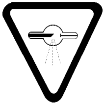
PART XVI[Revoked, SOR/88-471, s. 4]
- SOR/78-407, s. 2
- SOR/79-229, ss. 2(E), 3
- SOR/79-920, ss. 1 to 3
- SOR/80-381, s. 2
- SOR/80-464, s. 2
- SOR/81-23, s. 2
- SOR/81-286, s. 2
- SOR/81-545, s. 2
- SOR/82-542, s. 1
- SOR/82-981, s. 2
- SOR/83-495, s. 2
- SOR/84-930, ss. 1 to 5
- SOR/85-705, ss. 1, 2(F), 3(F), 4(F)
- SOR/85-756, s. 1
- SOR/85-757, ss. 1 to 3
- SOR/88-471, ss. 2(E), 3(E), 4
- SOR/91-408, s. 2(F)
- SOR/93-201, s. 2
- SOR/94-40, s. 1
- SOR/97-511, s. 2
- SOR/2001-252, s. 2
- SOR/2005-33, s. 2
- SOR/2006-122, ss. 1 to 6(F), 7, 8(F), 9(F), 10
- SOR/2014-25, ss. 1 to 3
- SOR/2017-228, s. 3
- SOR/2018-69, s. 86
- SOR/2022-197, s. 25
- SOR/2024-196, s. 4
Page Details
- Date modified: